Part Modeling > Engineering Features > Chamfer > Advanced Topics > Piece Management > About Chamfer Placement Ambiguity
  
About Chamfer Placement Ambiguity
As you work with chamfers, you may encounter a situation when more than one possible placement location exists for the current chamfer set. This can happen when two surfaces intersect in multiple, distinct locations. If this situation occurs, placement ambiguity results in which the placement of the chamfer pieces is unclear due to the selected references and part geometry.
You can easily address placement ambiguity. The table below illustrates placement ambiguity and the method used to address it:
Placement Ambiguity
Ambiguity Type
Example
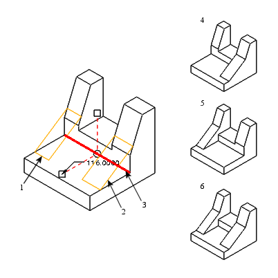
Chamfer Set Ambiguity
The chamfer set contains chamfer pieces that co-exist and can be placed in various locations given the selected references and part geometry. If this occurs, the chamfer set contains ambiguity.
Method: Use the Pieces tab. From the Pieces table, select the chamfer piece to exclude and select Excluded. All other pieces are Included by default.
1. Chamfer piece 1
2. Chamfer piece 2
3. Edge reference
4. Chamfer piece 2 excluded
5. Both chamfer pieces included