Example: Using Tool Kerf and CL Command
The following is an example of using the Tool Kerf and CL Command functionality in Follow Sketch motions.
1. Sketching plane
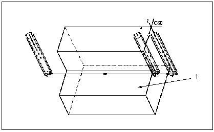
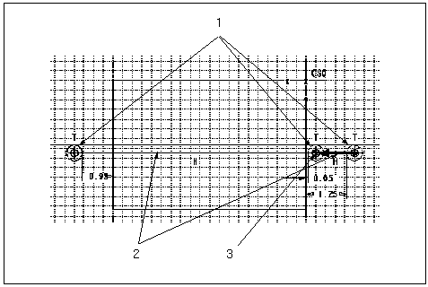
To produce the tool path shown above, where the tool machines the edge and stops right before touching the part to check gauge, create a Follow Sketch motion, as shown in the following illustration.
1. Add Tool Kerf entities and dimension as needed.
2. Sketch two tool motion segments between the Tool Kerf entities’ centers.
3. At the Tool Kerf center, add CL Command:
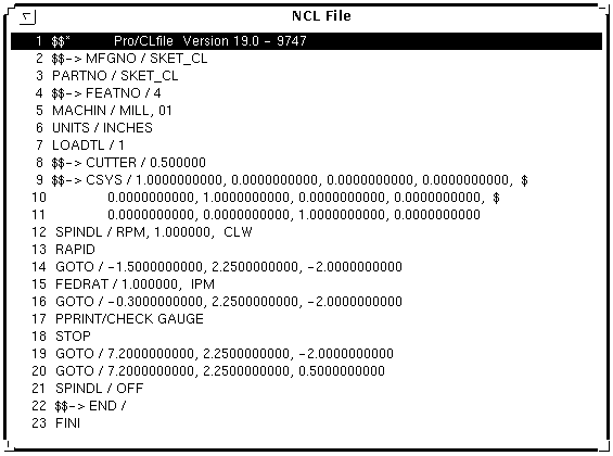
PPRINT / CHECK GAUGE
STOP
The resulting CL data is listed below:


