Example: Creating a Mill Window by Silhouette
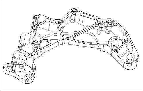
The easiest way to create a Mill Window for machining the part shown in the following illustration is to use the reference part silhouette. All the other methods would be much more time consuming because you would have to select multiple edges that form the part contour.
To create the Mill Window:
1. Click
Manufacturing >
 Mill Window
.
Creo NC activates the Mill Window tab.
2. Click silhouette window (

) as the window type, if this window type is not selected by default.
3. Use the Placement tab and create a datum plane offset along the z-axis of the CS0 coordinate system. Enter the offset value such that the datum plane is created above the top surface of the part.
|  If you create the Mill Window as part of an NC sequence setup, the above step is omitted because Creo NC automatically uses the NC sequence coordinate system and retract plane. |
4. Click

to create the Mill Window.
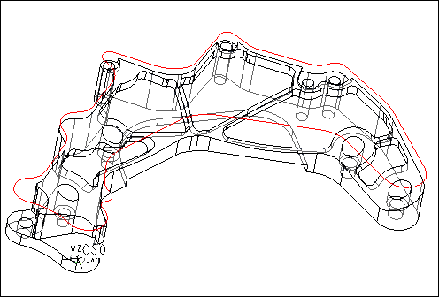
The resulting Mill Window is shown in the following illustration.


 Mill Window. Creo NC activates the Mill Window tab.
 ) as the window type, if this window type is not selected by default.
 to create the Mill Window.