Example: Manufacturing Criteria Name Usage in the Process Table
The following example illustrates how the features to be machined simultaneously are grouped based on the manufacturing criteria name.
Setting Up the Configuration Option
This manufacturing criteria usage in process table is driven by the udf_mfg_info_setup_file configuration option. You must set up this configuration option to point to a file with the .xml extension. This file stores the UDF-manufacturing criteria name mappings.
Defining Manufacturing Criteria Names (Creo NC)
After setting up the udf_mfg_info_setup_file configuration option, you must define the manufacturing criteria name.
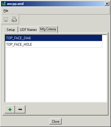
Click Tools > Mfg Criteria – UDF Files Setup in the Manufacturing Process Table. A dialog box opens. The name of this dialog box is the value that you have specified for the mfg_udf_info_setup_file configuration option. In this example the value for the mfg_udf_info_setup_file configuration option is C:\Creo\ancpp.xml. Enter the manufacturing criteria names as shown in the figure below.
Save the changes by clicking

and click
Close.
Inserting an Annotation Feature of type Manufacturing Template
Do the following:
1. Select the reference model in the Model Tree and click Open on the shortcut menu. The reference model opens in the Part mode.
2. Click
Annotate >
 Annotation Feature
. The
Annotation Feature dialog box opens with the
Definition tab active.
3. Click

on the
Definition tab. The
Mfg Template AE Setup dialog box opens.
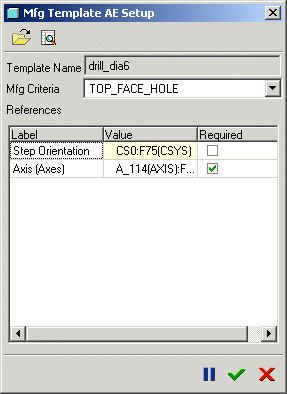
4. You are prompted to select the Mfg template that you want to use for the annotation feature. For this example, select drill_dia6 as the template and click OK.
5. Select the references for the template. For drill_dia6, select CS0:F75 as the coordinate system and A_114(Axis):F46(Hole) as the axis.
6. Select the manufacturing criteria for the selected references as TOP_FACE_HOLE as shown below.
7. Click

to close the
Mfg Template AE Setup dialog box. Click
OK to close the
Annotation Feature dialog box.
Viewing the Features to be Machined Based on the Manufacturing Criteria in the Model View
Switch to
Creo NC by selecting the manufacturing model on the
Window menu. Open the process manager. Click

. The
Mfg Template AE extraction dialog box opens. Click the
Model View tabbed page. In the
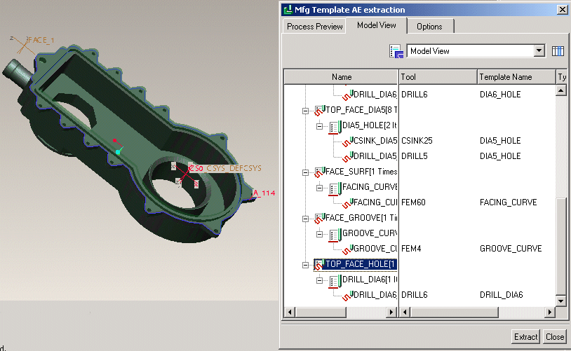
Model View tabbed page, steps are grouped by the Z-axis orientation, the manufacturing criteria, and the manufacturing template. Select
TOP_FACE_HOLE in the
Name column and click

. All the occurrences of the selected manufacturing criteria are highlighted in the model as shown below.


 and click Close.
 Annotation Feature. The Annotation Feature dialog box opens with the Definition tab active.
 to close the Mfg Template AE Setup dialog box. Click OK to close the Annotation Feature dialog box.
 . The Mfg Template AE extraction dialog box opens. Click the Model View tabbed page. In the Model View tabbed page, steps are grouped by the Z-axis orientation, the manufacturing criteria, and the manufacturing template. Select TOP_FACE_HOLE in the Name column and click
  . All the occurrences of the selected manufacturing criteria are highlighted in the model as shown below.