Automatic Synchronization of Start and End Points
The start and end points of a 4-Axis Wire EDM Automatic Cut motion can be automatically synchronized using the AUTOSYNCH_START_END parameter, available both at the NC sequence and the Customize levels. This functionality applies to 4-Axis Automatic Cut motions defined using the Contour1, Contour2, or Side Surfs options.
By default (AUTOSYNCH_START_END YES), the two heads will be automatically synchronized at the beginning and the end of each cut, as explained below.
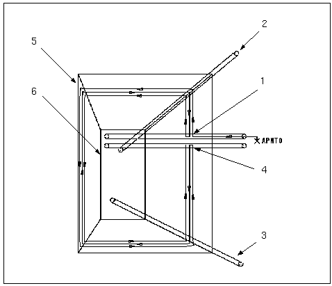
1. At the beginning of cut, the start of the 1st contour is auto synchronized with the closest point of the 2nd contour.
2. As the cut starts, use default synchronization.
3. Here, the default synchronization is still used.
4. At the end of cut, the end of the contour completed first is auto synchronized with the closest point of the other contour.
5. Lower contour
6. Upper contour
The illustration above shows how automatic synchronization works. The cut for the lower guide is the larger rectangular contour. The cut for the upper wire guide is the smaller contour. On the initial engagement of the wire to the lower contour, the upper contour will be synchronized automatically by finding the shortest distance between the two contours. As the wire goes around the profiles, they will automatically be synchronized by finding corresponding vertices on each. If the vertices are at tangent edges, you have an option to automatically synchronize the vertices between contours with the same number of entities by setting the AUTO_SYNCHRONIZE parameter to YES (the default is NO). You can also provide additional synchronization by manually specifying Synch points.
As the wire approaches the end of the pass on the cut motion, the endpoint synchronization will take effect. In this example, the wire will complete the upper contour before the lower contour; therefore, a synchronization point will be automatically made to swing the lower wire in line with the upper wire using the shortest distance between the two contours. The wire will then step in to the next pass and repeat the process.
|  If an approach is made on a non-planar surface (for example, a cone), orienting the wire axis as described above may cause a gouge because the axis may not line up with the u-v lines of the surface.  In this case, you will get a message: "WARNING: Approach is made on non planar surface and may cause gouge." Based on this warning, you can either set AUTOSYNCH_START_END to NO or change the Thread (Approach) point. |
If you set AUTOSYNCH_START_END to NO, the start and end points of the upper and lower contours will be mapped by cut entities; therefore, the upper and lower contours will have different start and end points in XY.

