Example: Modelling and Assembling AGCs
Example: Assembling Coordinate System AGCs
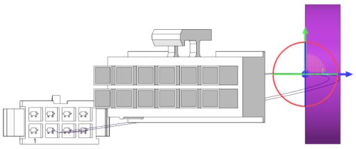
Refer the sample assembly to learn how to assemble AGCs that have a coordinate system so that they show correctly in the harness drawing.
Sample models are available at <Creo load point>\Common Files\help\sample_models\hmx\Grommet_model.
1. Open the GROMMET_MODEL.asm assembly.
2. Click
 Assemble
. The
Open dialog box appears.
3. Click grommet.prt and click Open. The grommet part appears in the graphics window and the Component Placement tab appears on the ribbon.
4. From the
 Saved Orientations
 choose
LEFT and position the grommet over the wires as shown in the figure.
5. From the
Saved Orientations choose
FRONT and position the grommet over the wires as shown in the figure.
6. From the
Saved Orientations choose
Top and position the grommet over the wires as shown in the figure.
7. Right-click and click Fix Constraint to place the grommet.
8. Click

on the
Component Placement tab.
9. Click
Applications >
 Cabling
 to open the
Cabling tab.
10. Right-click a cable, click
 Insert locations
 on the shortcut menu, and select the coordinate system
CSYS_PART_DEF of the grommet. The
Location tab appears.
11. Click
on the
Location tab to add the locations.
12. Click Components > Attach to Harness. The ATT HARN menu appears.
13. Click Add and select the grommet to attach to the flat harness. A message in the message area confirms that the component is attached to the harness.
14. Click Done/Return.
15. Click
Applications >
 Harness Mfg
. The
Harness Manufacturing Extension dialog box opens.
16. Click Flatten Harness.
|  You may have to change the value of the configuration option pro_unit_length to mm. |
Example: Modelling and Assembling Single Axis Components
Refer the sample models to learn how to model and assemble single axis associated geometry components so that they show correctly in the harness drawing. Sample models are available at <Creo load point>\Common Files\help\sample_models\hmx\Backshell_model..
1. Open as85049_88-xxnyy.prt and choose the generic instance.
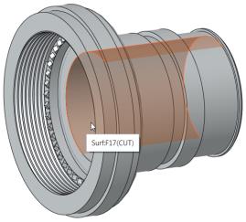
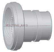
2. Create a datum axis through the surface Surf:17(CUT). Name the datum axis as ROUTING_AXIS.
3. From the Model Tree, right-click
ROUTING_AXIS and click
 Parameters
. The
Parameters dialog box opens.
4. Add a parameter BEND_ANGLE and define the following attributes:
◦ Type – REAL NUMBER
◦ Value – 0
5. Click OK to close the Parameters dialog box.
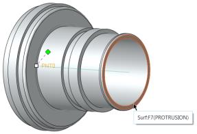
6. Click
 Point
Point to add a datum point on the routing axis at the entry orifice. The
Datum Point dialog box opens.
7. On the Placement tab, select the surface Surf:F7(PROTRUSTION) as Offset reference and type -0.02 in the Offset box.
| • If the units are set to inch, specify the offset distance as -0.02. • If the units are set to mm, specify the offset distance as -0.5. |
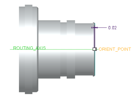
8. Click the Properties tab and type ORIENT_POINT in the Name box.
9. Save and close the model.
10. Open the BACKSHELL_MODEL.asm assembly.
11. Click
Assemble. The
Open dialog box appears.
12. Select
as85049_88-xxnyy.prt and click
 Open
Open. The
Select Instance dialog box opens.
13. On the By Name tab, click AS85049_88-21N02, and click Open.
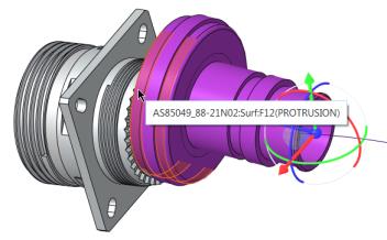
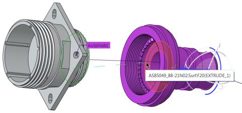
14. Assemble the component as follows:
a. Orient the component as shown in the figure and select the surface AS85049_88-21N02.
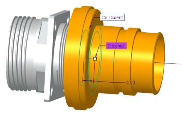
b. Click to select the surface D38999_20FG:Surf:F17(PROTRUSION) as shown in the figure. A coincident constraint is applied to the surfaces.
c. Click the surface as shown in the figure.
d. Click the surface AS85049_88-21N02:F20(EXTRUDE_1) as shown in the figure.
e. On the Component Placement tab, select Distance as the constraint and type 0.02as the value.
f. Click
on the
Component Placement tab. The AGC is attached to the harness model.
15. Click
Applications >
Cabling to open the Cabling mode.
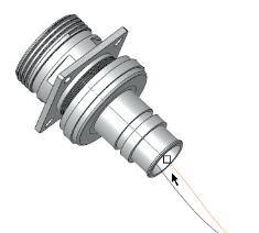
16. Select the cable, right-click, and click
Insert Locations. The
Location dialog box opens.
17. From the Model Tree select ROUTING_AXIS of the part AS85049_88-21N02.prt.
18. Insert a location as shown in the figure.
19. Click Components > Attach to Harness. The ATT HARN menu appears.
20. Click Add and select AS85049_88-21N02.prt. A message in the message area confirms that the component is attached to the harness.
21. Click Done/Return. The components are attached to the 3D harness assembly.
22. Click
Applications >
Harness Mfg. The
Harness Manufacturing Extension dialog box appears.
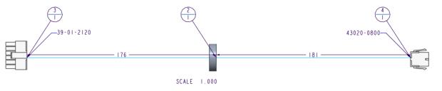
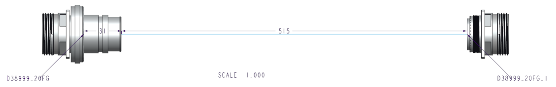
23. Click Flatten Harness. The harness manufacturing drawing is generated.
| • You may have to change the value of the configuration option pro_unit_length to mm. • If the position of the branch segments on the harness drawing is edited, the AGCs with move with the primary geometry. |
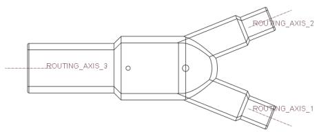
Example: Modelling and Assembling Multi Axis Components
Refer the sample models to learn how to model and assemble multi axis associated geometry components so that they show correctly in the harness drawing. Sample models are available at <Creo load point>\Common Files\help\sample_models\hmx\Y-Manifold_Model.
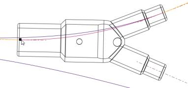
1. Open the382a0xx.prt part and select the generic instance.
2. Define routing axes through the center of all orifices of the AGC as shown in the figure.
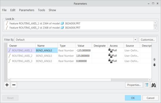
3. Select all the routing axes, right-click, and click
Parameters. The
Parameters dialog box opens.
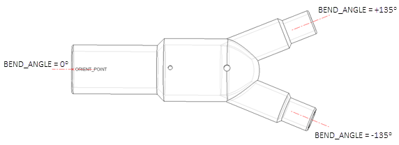
4. Add a parameter BEND_ANGLE and define the following attributes:
◦ Type – REAL NUMBER
◦ Value – 135, -135, and 0
5. Click
OK to close the
Parameters dialog box.
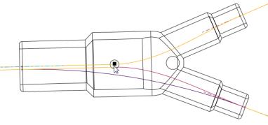
6. Click
Point to add a datum point on the routing axis at the entry orifice. The
Datum Point dialog box opens.
7. On the Placement tab, select the surface Surf:F6(PROTRUSTION) as Offset reference and type -0.02 in the Offset box.
| • If the units are set to inch, specify the offset distance as -0.02. • If the units are set to mm, specify the offset distance as -0.5. |
8. Click the Properties tab and type ORIENT_POINT in the Name box.
9. Save and close the model.
10. Open y_manifold_asm.asm assembly.
11. Click
Assemble. The
Open dialog box appears.
12. Select 382a0xx.prt and click Open. The Select Instance dialog box appears.
13. Select instance 382A023 and click Open.
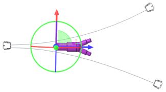
14. From the
Saved Orientations choose
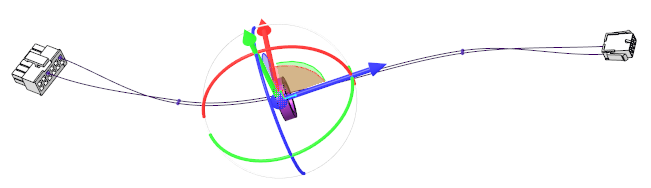
FRONT and position the component over the wires as shown in the figure.
15. From the
Saved Orientations choose
TOP and position the component as shown in the figure.
16. Right-click and click Fix Constraint.
17. Click
on the
Component Placement tab to place the AGC.
18. Click
Applications >
Cabling to open the Cabling mode.
19. Right-click wire
W1 and click
Insert Locations. The
Location dialog box appears.
20. From the
Saved Orientations choose
TOP.
21. From the Model Tree, select the upper routing axis and drag the location towards the exit as shown in the figure. Click
on the
Location tab to insert the location.
22. Right-click wire
W1, click
Insert Locations . The
Location dialog box appears.
23. From the Model Tree, select
ROUTING_AXIS_3 and drag the location towards the exit as shown in the figure. Click
on the
Location tab to insert the location.
24. Right-click wire
W2, click
Insert Locations. The
Location dialog box appears.
25. From the Model Tree, select the lower routing axis and drag the location towards the exit. Click
on the
Location tab to insert the location.
26. Select wire
W2, right-click and click
Insert Locations, and select the location on wire
W1 on the
ROUTING_AXIS_3. Click
on the
Location tab to insert the location.
27. Select wire
W1 right-click and click
Insert Locations.
28. From the Model Tree, select
ROUTING_AXIS_3 and drag the location towards the intersection point of the three axes. Click
on the
Location tab to insert the location.
29. Select wire
W2, right-click and click
Insert Locations, and click the location created in the previous step. Click
on the
Location tab to insert the location.
30. Click Components > Attach to Harness. The ATT HARN menu appears.
31. Click Add and select the 382A023.
32. Select the location points created at the intersection of the routing axis. The component is attached to the 3D harness assembly.
33. Click Done/Return.
34. Click
Applications >
Harness Mfg. The
Harness Manufacturing Extension dialog box opens.
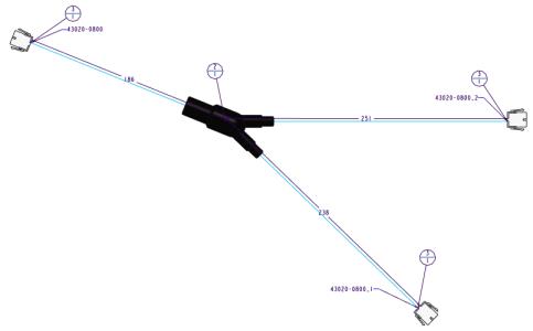
35. Click Flatten Harness. The flattened harness manufacturing drawing is generated.
| You may have to change the value of the configuration option pro_unit_length to mm. |