About Setting Up the Model
Board Outline
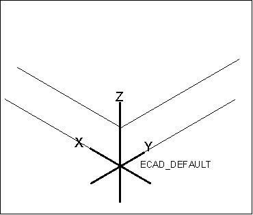
A board outline is usually created by the mechanical engineer. To ensure the proper transfer of information to the ECAD engineer, the board must have the following features as illustrated in the figure below.
• The bottom of the board should coincide with the xy-plane of the ecad csys.
• The z-axis positive direction is from the bottom of the board to the top.
You can incrementally update the board outline without a bend, with only the board thickness using EDMD IDX.
Holes
When holes are imported as either regular holes or light weight holes they are assigned a unique id for tracking during collaboration. It is recommended to use light weight holes when you have a large number of holes. When holes overlap, set the ecad_outline_holes_exp_method to arcs for proper export.
Pin holes are not moved with a component and it is recommended to import them only at the end of the design process. Pin holes are ignored during export to EDMD IDX, and are only updated during import.
Mechanical mounting holes are not moved with a component, but can be shown in the design process. It is recommended to create them on the ECAD side when they are part of the ECAD symbol. This insures synchronization of IDs.
Holes created in the ECAD or MCAD tool are assigned a unique id for collaboration.
ECAD Areas
Areas created in the ECAD or MCAD tool are assigned a unique id for collaboration.
Components
When you create a component model it is imperative that the origin and pin 1 of the model align with the 2D ECAD layout symbol. The origin can be set in the center of the component or on pin 1, but the decision should be consistent. The name of the placement coordinate system is referred to by the ecad_comp_csys_def_name configuration option and should be consistent as well. Failure to validate component placement and orientation could result in unintended, costly design errors.
Defining accurate models, allows the MCAD engineer to maximize available board space, at times this could result in reducing the size of the board. Using an ecad_hint.map file, you can replace generic outlines with fully defined models on import.