External Air Flow for a Truck: Exercise 3—Preparing the Mesh
A mesh is a computational grid inside, outside, or both inside and outside any closed geometry defined by a CAD surface.
Generating the Mesh
1. In the Flow Analysis Tree, select Domains.
2. In the Properties panel, Mesh tab under  Creo Flow Analysis tree, set the following values for Mesh Generation:
Creo Flow Analysis tree, set the following values for Mesh Generation:◦ Mesh Location—Exterior Volumes
◦ Bounding Box Margins—Nonuniform
▪ Maximum Side Sizes — 2.0, 1.2, 1.5
▪ Minimum Side Sizes — 0.3, 0, 1.5
◦ Minimum Cell Size — 0.0005
◦ Refine Zone Options—Box Zone Refinement
▪ Cell Size — 0.005
▪ First Corner — -9.0, -1.0, -1.5
▪ Diagonal Corner – 11.0, 4.0, 1.5
◦ Setup Options — Advanced Mode
◦ Sub-feature Options — Combined with Patches
3. Click  Generate Mesh to create the mesh for the fluid domain.
Generate Mesh to create the mesh for the fluid domain.4. In the Post-processing group, click  Section View.
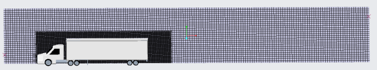
Section View.5. The Section 01 Properties appears. Set values for the options as listed below:
◦ Type—Plane Z
◦ Position—0
6. In the Properties panel, View tab, for Grid select Yes. The mesh for the section appears, as shown in the figure above.