Mixing Tank: Exercise 3—Preparing the Mesh
A mesh is a computational grid inside, outside, or both inside and outside any closed geometry defined by a CAD surface.
Generating the Mesh
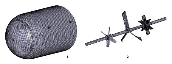
• 1 = Stator
• 2 = Rotor
1. In the Flow Analysis Tree, select  Domains.
Domains.2. In the Properties panel, Mesh tab, for Mesh Generation, type the following values:
◦ Maximum Cell Size — 0.01
◦ Minimum Cell Size — 0.001
◦ Cell Size on Surfaces — 0.01
The values are retained as default settings. You can change these if required.
3. Click  Generate Mesh to create the mesh for the fluid domain.
Generate Mesh to create the mesh for the fluid domain.4. Select Domains. in the Flow Analysis Tree. In the View tab of the Properties panel, select Yes for Grid. The domain mesh is created, as shown in figure. The FLUID_ROTOR boundary mesh is also shown in the figure above.
Domains. in the Flow Analysis Tree. In the View tab of the Properties panel, select Yes for Grid. The domain mesh is created, as shown in figure. The FLUID_ROTOR boundary mesh is also shown in the figure above.5. Right-click FLUID_ROTOR/FLUID_STATOR under Interface in General Boundaries and select Separate and Connect.
Viewing the Mesh
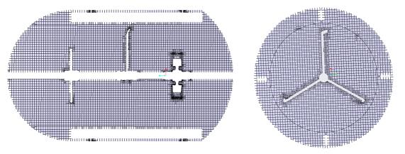
• 1 = Section 01
• 2 = Section 02
1. In the Post-processing group, click  Section View. The Section 01 Properties dialog box appears.
Section View. The Section 01 Properties dialog box appears.2. Set values for the options as listed below:
◦ Type — Plane Y
◦ Arbitrary Plane — 0
3. A new entity Section 01 appears under Derived Surfaces in the Flow Analysis Tree. Select Section 01.
4. In the Properties panel, View tab, set Grid, and Outline to Yes. The mesh for the section appears in the graphics window.
5. In the Post-processing group, click Section View. The Section 02 Properties dialog box appears.
Section View. The Section 02 Properties dialog box appears.6. Set values for the options as listed below:
◦ Type — Plane Z
◦ Arbitrary Plane — 0.575
7. A new entity Section 02 appears under Derived Surfaces in the Flow Analysis Tree. Select Section 02.
8. In the Properties panel, View tab, set Grid, and Outline to Yes. The mesh for the section appears in the graphics window.