Cyclone Separator with Particle Separation: Exercise 1—Extracting the Fluid Domain
Fluid domain extraction is the creation of a closed geometric region that surrounds the fluid.
1. Click > and navigate to the Advanced_FlowAnalysisModels folder. Click OK.
2. Click >  Open.
Open.
Open.3. From the File Open dialog box, browse to the cyclone_assembly folder and select cyclone_4.asm. Click Open.
4. Click  in the Graphics toolbar to display the style elements. Select Shading, or
  Shading with Edges.
in the Graphics toolbar to display the style elements. Select Shading, or Shading with Edges.5. Click the Applications tab.
6. Click  Flow Analysis. The Flow Analysis tab opens.
Flow Analysis. The Flow Analysis tab opens.7. Click  New Project. The New Project dialog box opens. Enter the name of the project and Click OK.
New Project. The New Project dialog box opens. Enter the name of the project and Click OK.8. Click  Create Fluid Domain. The Fluid Domain Creation tab opens. Two surfaces appear in the Surface Sets dialog box, under Included surfaces.
Create Fluid Domain. The Fluid Domain Creation tab opens. Two surfaces appear in the Surface Sets dialog box, under Included surfaces.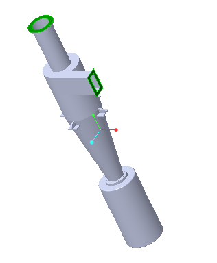
Adding the Simulation Domain
1. In the Fluid Domain Creation tab select Add to Simulation.
2. Click  to create the fluid domain. CYCLONE_4_FLUID_1.PRT appears in the Model Tree and CYCLONE_4_FLUID_1:Body 1 is added under Domains.
to create the fluid domain. CYCLONE_4_FLUID_1.PRT appears in the Model Tree and CYCLONE_4_FLUID_1:Body 1 is added under Domains.The boundary conditions BC_00001 and BC_00002 are automatically created and they appear in the Flow Analysis Tree under  Boundary Conditions >
  General Boundaries. CYCLONE_4_1_FLUID appears in the Flow Analysis Tree under > > .
Boundary Conditions > General Boundaries. CYCLONE_4_1_FLUID appears in the Flow Analysis Tree under > > .3. Right-click BC_00001 and select  Rename.
Rename.4. In the New name box, type Outlet.
5. Right-click BC_00002 and select Rename.
Rename.6. In the New name box, type Inlet and click OK.