Modeling Fasteners—Connecting Shells
To create a fastener between shells you need to select Connecting Shells on the Fastener Definition dialog box.
The fasteners can be point-to-point or edge-to-edge.
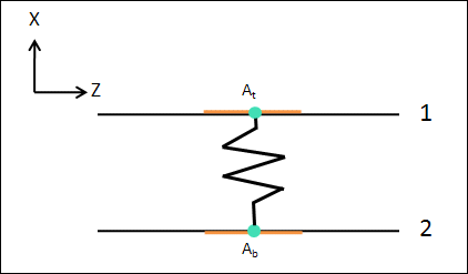
Modeling of a point-to-point fastener between two shell surfaces is shown in the following figure:

1. top shell surface
2. bottom shell surface
The fastener is modeled as a spring between the two points. At and Ab. The ends of the spring are connected with weighted links to the orange discs on the top and bottom shell surfaces. The discs have a diameter equal to the value specified in the Fastener Head and Nut Diameter box.
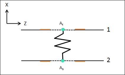
Modeling of an edge-to-edge fastener between two shells is shown in the following figure:

1. top shell surface
2. bottom shell surface
The fastener is modeled as a spring between the centers of the selected circular edges on each shell surface. The ends of the spring are linked with weighted links to the discs shown in orange. The outer diameter of the discs has the value specified in the Fastener Head and Nut Diameter box. The inner diameter is the fastener shaft diameter.
If you define fastener stiffness using the Using spring stiffness property option, the stiffness is calculated using all the spring stiffness properties that you define. You must provide suitable values in order to model the fastener stiffness correctly.
If you define fastener stiffness using the Using diameter and material option then fastener stiffness is set to the stiffness of a Timoshenko cylindrical beam that has the specified material and diameter. The length of the beam is the distance between the two reference points or reference edges.
The following measures are automatically generated for a fastener connecting two shells. The measures are displayed on the Model Tree. Measure values are calculated for the spring between At and Ab. Axial forces are along the X-axis and shear forces are along Y- and Z-axes.
When you run an analysis you can view the measure values in the summary file.
Measure Name | Description |
|---|---|
fastenerName_shear_force | Shear force for a fastener. It is calculated only if you select Frictionless Interface. In this case the fastener carries all the shear force since there is no friction between the two components. |
fastenerName_shear_stress | Shear Stress in a fastener. It is calculated only if you select Frictionless Interface and define stiffness using the Using diameter and material option. |
fastenerName_axial_force1 | Axial force in a fastener. |
fastenerName_axial_stress | Axial stress in a fastener. It is calculated only if you define stiffness using the Using diameter and material option. |
fastenerName_bending_moment | Bending moment in a fastener. |
fastenerName_bending_stress | Bending stress in a fastener. It is calculated only if you define stiffness using the Using diameter and material option. |
fastenerName_torsion_moment | Torsional moment in a fastener. It is calculated only if you select Frictionless Interface. In this case the fastener carries all the torsional moment since there is no friction between the two components. |
fastenerName_torsion_stress | Torsional stress in a fastener. It is calculated only if you define stiffness using the Using diameter and material option and select Frictionless Interface. In this case the fastener carries all the torsional stress since there is no friction between the two components. |