Shell Pairs—Creo Ansys Simulation
Shell pairs are used to model thin walled areas of a model as shells rather than solids for simulation. The defined shell pairs are compressed to a shell surface (sometimes also called a “mid surface” because it is usually placed mid-distance between the shell pair surfaces.) During meshing of the model the shell elements are placed on this compressed shell surface. In order to maintain the design intent and integrity of the model, you might have to connect and disconnect shell pairs to and from other shells, solids and beams, using either contacts or weld features.
You can create shell pairs using one of the following methods:
• Automatically detect shell pairs
• Manually define shell pairs
Automatically Detect Shell Pairs
When you use this option the software automatically detects all shell pairs within the model that are separated by a distance less than or equal to a specified value. This method can also automatically create shell pairs based on feature creation methods.
1. Click the Refine Model tab. Click the arrow below Shell and then click  Detect Shell Pairs to open the Auto Detect Shell Pairs dialog box.
 Detect Shell Pairs to open the Auto Detect Shell Pairs dialog box.
2. Select bodies or components for which you want to detect shell pairs.
3. Select the Use geometry analysis check box selected if you want the software to automatically detect pairs based on the model geometry as well as feature creation methods. If this check box is cleared, then shell pairs are detected based only on feature creation methods.
4. If you have selected the Use geometry analysis check box, then specify a value in the Thickness box as the threshold value for automatically detecting all pairs of opposing surfaces that are at a distance less than this value. Select a unit for thickness.
5. Click OK to create shell pairs. The names of the created shell pairs are assigned automatically.
To Define Shell Pairs Manually
1. Click the Refine Model tab. Click the arrow adjacent to Shell and then click Shell Pair to open the Shell Pair Definition dialog box.
2. Specify a name for the shell pair or retain the default name.
3. Select surfaces for which you want to define shell pairs. If the Auto select opposing surfaces check box is selected, the software automatically selects the opposing surface as the other surface in the shell pair. Clear the Auto select opposing surfaces to manually select the opposing surface. Your selection is displayed in the References collector.
4. Select the surface on which to place the compressed shell surface. The default is the mid surface that is mid way between the top and bottom surface, with the thickness of the shell distributed equally in both directions. Select Top to place the compressed surface on the top surface of the shell pair, or select Bottom to place the compressed shell surface on the bottom surface of the shell pair.
The top surface is the first surface selected for a shell pair, and the bottom surface is the second surface that you select, or that is automatically selected. When you select Top, the direction of thickness is towards the bottom surface. When you select Bottom the direction of thickness is towards the top surface. |
5. Clear or select the Extend to adjacent surfaces check box if there is solid-shell compression due to the creation of a shell pair. If you clear the check box the source surface is extended with the use of additional edges, where the angle between the source and adjacent surfaces is less than 30 degrees.
6. Select the material for the shell pair. If a part has a material assigned to it , the part material is selected by default. Click More to open the Materials dialog box and select a suitable material.
You must only select linear isotropic materials for shells. |
7. Click Repeat to create the shell pair and retain all options for the next shell pair that you want to create.
Click OK to create the shell pair and close the dialog box.
8. To review or check shell compression in the model click > . Ensure that the Shell surfaces check box is selected. Click Apply to view the compressed shell pairs in the model.
Adjust Tangent Pairs
When multiple shell pairs are defined for a model, and if shell pairs that are tangential to one another have different placement defined for the compressed surface, then during compression the resulting compressed geometry may not be continuous. Meshing or reviewing of geometry might fail. In this case you can use the Adjust Tangent Pairs option to change the placement of the compressed shell of adjacent shell pairs to match that of a selected shell pair. The following example illustrates the use of the Adjust Tangent Pairs command.
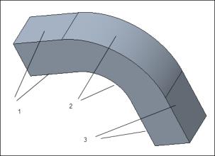
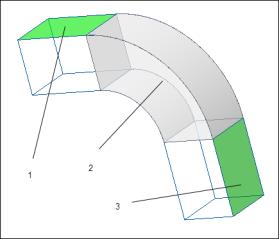
Consider the following model that has three shell pairs defined. The first and third shell pair have the compressed surface placement defined as the top surface, while the second shell pair has the compressed surface defined as the midsurface.
 1. Shell Pair 1 2. Shell Pair 2 3. Shell Pair 3 |  1. Compressed surface placement —top 2. Compressed surface placement —midsurface 3. Compressed surface placement —top |
When you try to mesh the model, or run a study check, compression fails as the resulting compressed geometry is not continuous. In this case if you want to place all the compressed surfaces at the same position as the second shell pair, then do the following:
1. Select the second shell pair from the Model Tree.
2. Right-click and select Adjust Tangent Pairs.
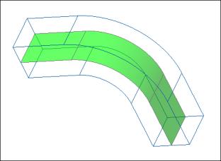
The placement of the compressed surface for the first and third shell pairs is changed to the placement of the second shell pair. In this example the new placement is the mid surface. Meshing, reviewing geometry or running a study check will now work. The compressed shell pair is as shown in the figure below:

Note that the Adjust Tangent Pairs command works only for tangent pairs within the same body.
Study Checks for Shell Pairs
When you use shell pairs within a model, there are some potential sources of problems that you must know about.
• Simulation objects could reference several solid geometries some of which belong to shell pairs; these objects will end up having mixed reference types. These are usually not supported in Creo Ansys Simulation.
• On compression, some simulation objects that reference shell pair geometry may cause conflicts.
• Some simulation objects that reference shell pair geometry may become invalid upon compression. This may also occur if a definition referencing side surfaces or thickness edges is invalid when referencing edges or vertices, respectively.
• Shells and beams are not supported for Thermal studies.
Before you run a simulation study it is a good practice to run a study check to identify issues in models with shell pairs.
 Review Geometry