Bearing Loads—Creo Ansys Simulation
Bearing loads are used to model the force transmitted between a pin and a hole that are closely fitted together. You can define bearing loads in Creo Ansys Simulation to model the radial forces acting on the plane at right angles to the axis of rotation of a cylindrical surface. The software applies the force distribution automatically as a parabolic function over half (or a smaller part of ) a cylinder in the radial direction only.
You cannot define the axial component of force for a bearing load. In the figure below the axis of the cylindrical surface is along the Z- direction so you cannot have a Z- load component for the bearing load. You can only define radial forces for the XY- plane. If you want to model the axial component of force for the bearing load you can define a force load to represent it instead.
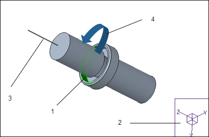
1. Cylindrical surface on which the bearing load is created
2. Reference Coordinate System
3. Z- direction —The axial component of bearing load cannot be defined.
4. Direction of radial force about the X-Y plane
When you apply bearing loads to shared references the results are additive. You must apply a separate bearing load to each hole instead of applying a single load to multiple holes.
To Define a Bearing Load
1. Within a structural simulation study, click >  Bearing. The Bearing Load dialog box opens.
Bearing. The Bearing Load dialog box opens.2. Specify a name for the load, or use the default name. Optionally click the color swatch adjacent to the Name box to change the color of the icon, the distribution, or the text displayed for the load.
3. Select a solid cylindrical surface or part of a cylindrical surface on which to create the bearing load. Your selection appears in the References collector. If you select half of a full cylinder, both halves are selected and considered as a single reference.
4. The default coordinate system of the model is the reference coordinate system and is displayed in the Coordinate system collector. In the case of an assembly, the coordinate system of the top level assembly is the default coordinate system. If the model does not have a default coordinate system then the Coordinate system collector is empty.
You can select an alternative reference coordinate system from the Model Tree or Graphics Window.
Click  to return to using the default coordinate system of the model. If the model does not have a default coordinate system then the button is not available.
to return to using the default coordinate system of the model. If the model does not have a default coordinate system then the button is not available.5. Select one of the following options to define the magnitude and direction of the load:
◦ Magnitude and direction—Select one of the following Direction by options to define the direction of the load:
▪ Direction Vector—Specify the value of the unit vectors for direction by typing a value of 0, 1, or -1 in the X, Y, or Z field.
▪ Reference—Select a planar surface or a linear edge. The direction of the load mimics the direction of the reference.
Specify the magnitude of the load in the Magnitude entry box.
◦ Directional components—Specify the components of the load for each coordinate direction X, Y, or Z. The resultant direction and magnitude of the load is determined from the values you specify for each coordinate. If you enter a positive value the load component is applied in the same direction as the coordinate system axis. If you use a negative value, the direction of the load opposes the coordinate system axis.
6. Select units of force from the list or accept the default units.
7. Click OK to create the load and save it.