To Create Formula-driven Lattice
You can select a mathematical formula to define the cell shape. The lattice uses a volumetric representation. The quality of formula-driven lattice depends on the part accuracy, the level of accuracy of the volumetric representation, and the lattice wall thickness.
1. Click >  Lattice. The Lattice tab opens.
Lattice. The Lattice tab opens.2. On the Lattice tab, define these settings:
a. Next to Lattice type, select  Formula Driven.
Formula Driven.b. To define the direction with which the z-axis of the cell is aligned, under Cell Direction, select Z, X, or Y.
c. To set the size of the lattice relative to the current size of the cell, under Cell Scale, type a value, and press ENTER.
d. To set the level of accuracy of the volumetric representation, next to Accuracy, select an option. This defines the volumetric size and density. The higher the level of accuracy, the better the volumetric resolution, at the expense of regeneration time.
4. For lattice that does not replace a body, you can define the body to which the feature is added. Click the Body Options tab, and perform one of the following actions:
◦ To add geometry to an existing body, click the body collector, and then select the body to which geometry is added.
◦ To create the feature in a new body, select the Create new body check box. The name of the new body appears in the body collector.
5. To divide the volume into three zones, creating one body for the main formula-driven lattice, and two construction bodies that represent the complementary empty zones, one on each side of the main formula-driven lattice wall, on the Body Options tab, select the Create complementary bodies check box.
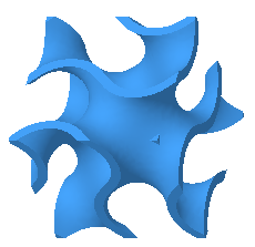
Single cell of formula-driven lattice:
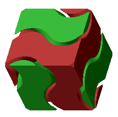
Two complementary zones are created by the lattice, one on each side of the lattice:
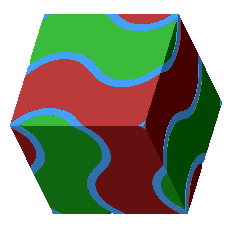
Lattice dividing the space into complementary zones:
6. Click the Cell Type tab, and define the structure of the cells:
a. Under Function, select a formula to drive the cell shape:
▪ Gyroid—Governed by the formula
sin(x) cos(y) + sin(y) cos(z) + sin(z) cos(x) = 0

▪ Primitive—Also known as Schwarz P type, governed by the formula
cos(x) + cos(y) + cos(z) = 0

▪ Diamond—Also known as Schwarz D type, governed by the formula
sin(x) sin(y) sin(z) + sin(x) cos(y) cos(z) + cos(x) sin(y) cos(z) + cos(x) cos(y) sin(z) = 0

b. Next to Cell size, define the X, Y, and Z dimensions of the cell. These are the absolute cell dimensions, using the model units.
7. Click the Cell Fill tab, define these options:
a. Next to Wall thickness, define the thickness of the cell walls.
b. To define how to handle geometry that, due to trimming the lattice cell, is not attached to the lattice or to solid geometry at intersections with the volume region, in the Unattached geometry list, select an option:
▪ Keep—Keeps all unattached geometry.
▪ Remove—Removes all unattached geometry.
8. To define regions that vary within the lattice volume, and the related parameters, click the Density tab, click  References, and perform either of the following actions:
References, and perform either of the following actions:◦ To define regions of varied thickness:
a. To define the thickness below which lattice is not created, next to Wall thickness cutoff, type a value.
b. Under Set Settings, click New set. The References collector becomes available.
c. Select references from which distance is measured:
▪ Point—Defines a spherical volume region, with a radius equal to the distance value.
▪ Curve—Defines a cylindrical sweep volume region, with a radius equal to the distance value.
▪ Surface, quilt, vertex, or coordinate system origin—Defines a volume region that is offset by the distance value.
d. Next to Variability of, select Thickness,
e. To define the distance from the reference where the varied thickness is created, next to Distance, type a value. This distance determines the size of the volume region around the reference you chose.
f. To set the thickness of the lattice wall at the selected reference, next to Target wall thickness, type a value.
g. To set the rate of change for the thickness, next to Size change rate, type a value.
When the rate = 1, the rate of change is linear.
When the rate < 1, the rate of change is slower than linear.
When the rate >1, the rate of change is faster than linear.
◦ To define regions of varied wall offset, useful in creating structures that direct flow like baffles:
a. Under Set Settings, click New set. The References collector becomes available.
b. Select references from which distance is measured:
▪ Point—Defines a spherical volume region, with a radius equal to the distance value.
▪ Curve—Defines a cylindrical sweep volume region, with a radius equal to the distance value.
▪ Surface, quilt, vertex, or coordinate system origin—Defines a volume region that is offset by the distance value.
c. Next to Variability of, select Wall Offset,
d. To define the distance from the reference where the varied wall offset is created, next to Distance, type a value. This distance determines the size of the volume region around the reference you chose.
e. To set the offset of the lattice wall at the selected reference, next to Target wall offset, type a value.
f. To set the rate of change for the offset, next to Offset change rate, type a value.
When the rate = 1, the rate of change is linear.
When the rate < 1, the rate of change is slower than linear.
When the rate >1, the rate of change is faster than linear.
For more information, including recommended parameters for creating baffles, see About Lattice with Varied Wall Offset.
9. Click  OK.
OK.
OK.