Stackup Details Table
Click  next to the Stackup in the Summary table to open the Stackup Details table:
next to the Stackup in the Summary table to open the Stackup Details table: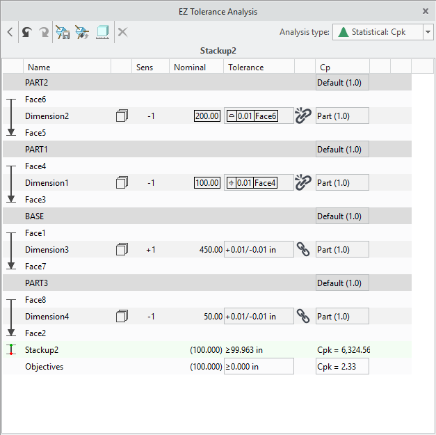
A description of the Stackup Details table follows:
• The graphical symbols in the first column indicate the dimension path through these parts and features. Each feature is represented with a symbol that indicates the type, such as a flat surface, a cylindrical feature of size, or a planar feature of size such as a slot.
The previous image shows how the dimension attaches to the feature. For features of size, you can modify the assumed attachment. Many dimensions, however, are attached to the planar surfaces with no ability to modify the attachment option. Click the highlighted box in the first column of a dimension row to open the Attachment dialog box. Select an attachment type from the list.
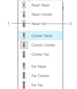
1. Indicates where the dimension origin should be attached to the size of the feature above the dimension row.
2. Indicates where the dimension should be attached to the size of the feature below the dimension row.
When both the feature above and below the dimension are features of size, the list has nine options. If only one of the features is a feature of size, the list has three options.
You cannot change the attachment for dimensions with tolerances linked with tolerances on the part files. To change the attachment type of such dimensions, you must first unlink them.
• Name—Name of the part, feature, dimension, calculated assembly shift, or calculated datum shift. The second last row shows the name of the Stackup.
•  —A dimension is used in more than one Stackup. Place the pointer on this icon to open the list of Stackups in which the dimension is used.
—A dimension is used in more than one Stackup. Place the pointer on this icon to open the list of Stackups in which the dimension is used.• Sens—Sensitivity and direction of the dimension in the Stackup. It is 1 or -1. If the dimension loop passes from the outer edge to the center of a feature of size, it is ½ or -½.
• Nominal—Nominal value of the dimension between the two features calculated from the geometry. You can edit the nominal values for the offsets that are added between parts using the Add Offset tool. Click the value to open the Edit Tolerance dialog box and edit the value.
• Tolerance—Type and value of a tolerance objective. Click the tolerance to open the Edit Tolerance dialog box. Select a tolerance type for defining the upper and lower objectives of the Stackup. The following types are supported:
◦ ± (symmetric)—Bilateral value applied relative to the nominal value.
◦ +/- (plus-minus)—Non-symmetric values applied relative to the nominal value. The +/+ and -/- definitions are supported.
◦ Limits—Definition of absolute upper and lower limits for the objective independent of the nominal value.
◦ ≤ (upper limit)—Definition of a single upper limit.
◦ ≥ (lower limit)—Definition of a single lower limit.
◦ Geometric Tolerance—See To add geometric tolerance.
• In the specified objective values, the number of digits determine the precision to be used. However, if you specify a value without a decimal, the precision is not changed. • The sign and value of the number that you specify are evaluated to determine if it must be placed in the upper or lower segment of +/- and Limits objective types. If you do not specify a sign, the existing sign designated for the field is applicable. |
•  (link) or
  (break link)— In feature or dimension rows, appears when either of the following conditions are met:
(link) or (break link)— In feature or dimension rows, appears when either of the following conditions are met:◦ When the dimension in the Creo EZ Tolerance Analysis Stackup is associated with the dimension in a Creo Parametric part.
◦ When two subsequent features in the Stackup are associated with a Datum Feature and an annotation controls the other feature back to the Datum Feature.
Creo EZ Tolerance Analysis uses the tolerance information found in Creo Parametric and creates a link. Changes made to the tolerances in Creo EZ Tolerance Analysis, result in changes in the associated tolerance in the Creo Parametric part file.
To change the tolerance without updating the tolerance values in the Creo Parametric part, click to break the link. replaces , indicating the link is broken. To restore the link, click . The tolerance displayed in Creo EZ Tolerance Analysis is pushed into the equivalent Creo Parametric part file.
to break the link. replaces , indicating the link is broken. To restore the link, click . The tolerance displayed in Creo EZ Tolerance Analysis is pushed into the equivalent Creo Parametric part file.• Cp—When the analysis type is either RSS or Statistical, indicates the Cp values for the parts and the dimensions. These Cp values are used to assume a standard deviation for the variation of each of the input dimensions for the calculation of the distribution characteristics of the Stackup result. For Statistical analyses, Creo EZ Tolerance Analysis incorporates a hierarchy of settings to give you control over the assumed statistical distributions. Only Normal or Gaussian distributions are supported, but you can control the standard deviation defined by the tolerance applied through the specification of an assumed Cp quality metric.
You can define the Cp quality metric at the following levels:
◦ Application level—Through the definition of Model Cp option in the Options dialog box. It is recommended to set this at 1.0 unless you have most of your parts produced at a different quality level.
◦ Part level—In the Stackup Details in the Cp column of the part row with tolerance included in the Stackup results. Until you specify a part-specific value, the part assumes the default value defined at the application level. This existing value of Model Cp appears in parentheses in the Cp column.
◦ Dimension and Feature level—In the Cp column of the dimension row with tolerance included in the Stackup results. Unless you specify a unique value for a specific dimension or feature, Cp defined at the part level is considered. In the Cp column, the current Cp value of the part is shown in parentheses. You cannot edit Cp values for RSS analyses.
To change the Cp metric level:
a. Click in the Cp column. The Cp Value dialog box opens.
b. Select the level from the Cp source list.
c. Specify the value in the Cp value box and click OK.
The rows in the table consist of the following:
• Parts—One or more parts are included in the Stackup definition. For each part, there is the following:
◦ Features—One or more features on the part appear in order of the Stackup loop passing through the part. Features of size have a size dimension and tolerance shown in the same row. When there are four or more features included for a part, you can change the order of all except the first and the last feature. For more information, see Adding Features.
◦ Dimensions and Tolerances—When two or more features are used from the part, a dimension between each indicates a tolerance and the distance that is the nominal dimension value between the features.
◦ Datum Shift contributors—When a datum feature is referenced at its Maximum Material Boundary or Least Material Boundary, an additional row appears with a light red background between the datum feature and the row with the Feature Control Frame. The value of tolerance in this row represents the permissible datum shift that can occur when the datum feature is at its ideal size, such as ½ way between the upper and lower specification limits for the size. Additional possible datum shift effects are accounted for in the modified sensitivity of the size dimension.
• Assembly Shift contributors — When Creo EZ Tolerance Analysis detects that a clearance can occur between the features that serve as the mating features of neighboring components, a row of a light purple background is shown in the Stackup table that controls how the assembly shift between the two parts is treated by the calculation. Assembly shift can occur, for example, between bolts and clearance holes or between slabs and slots. The assembly shift row includes an icon that indicates the current bias setting with a label beginning with “Asm shift”. It also lists the names of the two features being controlled.
The value of the tolerance in this row represents the permissible assembly shift that can occur in each direction when both features are at their "ideal" size (that is, ½ way between the upper and lower specification limits for their sizes). Additional assembly shift effects, which can occur as the features vary, are accounted for in the modified sensitivity of the respective size dimensions.
To change the bias of the shift row, click the arrow icon on the left side and choose the desired bias option from the drop-down list in the dialog box.
The assembly shift bias can be set to one of four values: Float, Minimize, Maximize, and Center.
Float- By default, the assembly shift is initially be set to Float. This represents the case where the mating features are nominally centered relative to each other, but are free to move about, as the clearance allows. The amount of clearance contributes as a tolerance to the overall results of the Stackup.
Minimize or Maximize- The assumption of random placement, represented by the bias option Float, means that there is nothing influencing the position of the parts relative to one another during the assembly. However, when trying to determine if two parts can be assembled, we often want to account for the fact that the person assembling the parts will move them around, using the clearances between the features described above, until they fit together. In such cases, instead of assuming a random placement of the bolt into the hole, we would want to use the clearance to maximize or minimize the distance being analyzed in the Stackup to better represent the actual assembly process.
When either Maximize or Minimize is selected, the tolerance display changes to a single value, in parentheses, indicating the amount of nominal bias. After making this change, notice a change in the Stackup nominal value to a larger value, for Maximize, or a smaller value, for Minimize, by the bias amount.
Note that the upper Worst Case and RSS limit will not be impacted when changing any shift row from Float to Maximize. Similarly, the lower Worst Case and RSS limit will not change when changing from Float to Minimize. This is because both analysis techniques already assume the part is shifted in the extreme positions when Float is applied.
Center- The Center bias option ignores the assembly shift for the purpose of the calculations, and instead treats the mating features as if there were no clearance between them. In other words, the Center bias option sets the two mating features to be nominally centered on each other and does not consider the clearance between them or the tolerances on their dimensions for the calculations. When set to Center the sensitivity of the assembly shift row is set to zero as are the size dimensions for the two mating features.
The Center bias option is typically used when the two features of size are modeled with the clearance in the CAD system, although the real parts do not have clearance or would otherwise not be allowed to shift at all during the assembly. For example, some companies choose to model threaded fasteners at the minor diameter and threaded holes at the major diameter to simplify the assembly-level interference checking. In this case, the fastener and hole in the CAD model might have a slight clearance but should be treated by a tolerance Stackup as though no interference exists, and the mating features will always be centered on each other with no ability to shift.
• Offsets between parts—If one or more offsets between two parts are defined in the Stackup with the Add Offset tool, each defined offset in a row is highlighted. Click the field to open the Edit Tolerance dialog box. Specify a new nominal value or a tolerance value. To remove the offset, click  in the table.
in the table.• Results—The second last row shows the results of the Stackup analysis based on the defined Target Quality level. The results are presented in the same format used for the Objective definition, such as ±, +/-, or Limits. When Target Quality is set to use one of the statistical methods, the Results row includes the calculated quality of the Stackup distribution compared with the defined Objective. For RSS, the row shows the Cpk label in the Cp column. For the general statistical analyses, Creo EZ Tolerance Analysis reports the Predicted Quality using the same metric type as defined for the Target Quality. Double-click the name to edit it, if required.
• Objectives—The last row in the table shows the Objective for the Stackup along with the Target Quality, such as the type of analysis and desired quality level for statistical analyses. You can change the analysis type and quality level.