Turning Parameters
The following parameters are specific to turning NC sequences. They are listed under a heading corresponding to the name of the branch when you set up the parameters.
For description of the common manufacturing parameters, available for all the NC sequence types, see the topic Common NC Sequence Parameters. Follow the link under See Also to access this topic.
|
|
• You must supply a value for all parameters that have a default of –1 (this means that the default value is not set by Creo NC).
• Length units for the NC sequence parameters (where applicable) are the same as the units of the workpiece.
|
Cut Option
SCAN_TYPE
For Area turning, specifies the type of tool movement and the way the tool scans multi-step profiles. You can specify one of the following values:
• TYPE_1—The tool cuts in one direction only, then retracts to the beginning of the cut. In case of multiple hollows, the tool completes the first hollow and goes to the next one.
• TYPE_2—The tool cuts back and forth along the whole length of the cut.
• TYPE_3—The tool cuts back and forth. In case of multiple hollows, the tool completes the first hollow and goes to the next one.
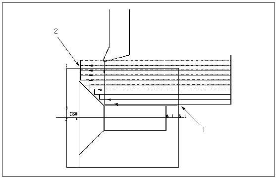
• TYPE_1_CONNECT—Works in the same manner as TYPE_1, except that the tool moves from one pass to the next by profiling the workpiece between the end point of the first pass and the start point of the following pass. If you specify the CONNECT_OVERLAP parameter, then after a pass the tool moves along the surface of the part for CONNECT_OVERLAP distance and subsequently moves to the start point of the following pass.
• ZIGZAG_AREA—The tool cuts back and forth along a zigzag path. The first pass cuts STEP_DEPTH distance deep and the last pass cuts END_STEP_DEPTH distance deep. END_STEP_DEPTH must always be smaller than STEP_DEPTH. The depths of the intermediate passes decrease gradually from STEP_DEPTH to END_STEP_DEPTH.
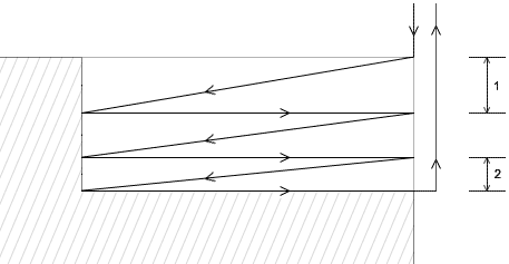 1. STEP_DEPTH 2. END_STEP_DEPTH |
• RAMP_RETRACT—Works in the same manner as TYPE_1, except that the tool cuts through the STEP_DEPTH distance in two passes. The first pass is angular, that is, the depth of cut gradually varies from RAMP_STEP_DEPTH at one end to zero at the other end. RAMP_STEP_DEPTH must always be smaller than STEP_DEPTH. The second pass is horizontal. The tool retracts to its original position after each pass.
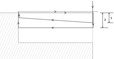 1. RAMP_STEP_DEPTH 2. STEP_DEPTH |
• RAMP_CONNECT—Works in the same manner as TYPE_2, except that the tool cuts through the STEP_DEPTH distance in two horizontal passes.
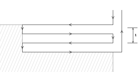 1. STEP_DEPTH |
• PLUNGE_RELIEF—Works in the same manner as TYPE_1, except that before each pass, the tool cuts a depth equal to PLUNGE_RELIEF_DEPTH.
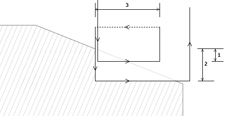 1. PLUNGE_RELIEF_DEPTH 2. STEP_DEPTH 3. PLUNGE_RELIEF_LENGTH |
• TYPE1_CONNECT_END— Works in the same manner as TYPE_1_CONNECT, except that after completing a pass, the tool moves to the end of the previous pass by profiling the workpiece.
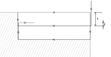 1. STEP_DEPTH 2. CONNECT_OVERLAP |
The following illustration shows the difference between TYPE_1 and TYPE_1_CONNECT.
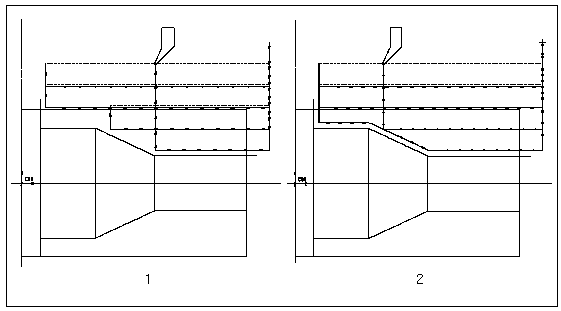
1. SCAN_TYPE—TYPE_1
2. SCAN_TYPE—TYPE_1_CONNECT
For Groove turning, SCAN_TYPE specifies if the tool cuts from the middle to the sides of the groove, or from one side to the other:
• TYPE_1 (the default)—Starts in the middle and makes alternating passes on each side in turn.
• TYPE_ONE_DIR—Starts at one side of the groove and moves to the other side.
• TYPE_ONE_WALL—Starts in the middle and makes alternating passes on the groove walls as well as the island walls within the groove, to the defined finished size.
• SIDE_TURN—Starts at one side of the groove and moves to the other side, taking the depth of the cut in each alternating pass as per the specified PECK_DEPTH.
• WIDTH_STRADDLE—Starts in the middle and makes alternating passes as per the specified PECK_DEPTH and the STEP_OVER values. It gives a clean cut at the end of each pass.
• PLUNGE_N_RAMP—Starts at one side of the groove and moves to the other side, plunging to the full depth of the groove profile on both sides. Subsequently, the tool alternates between an angular pass (with a RAMP angle) until the required cut is achieved. In this case, odd cuts are parallel to the depth of the groove and even cuts are angular.
• TYPE_1_CONNECT—Assures uniform stock allowance on the sides of the groove after the rough pass. Starts on the deepest portion of the groove, as close to the middle of the groove as possible, and makes alternating passes on each side in turn; continues making passes on the longer side, if necessary, until the wall is reached. Makes connecting motions between the plunge passes by moving along the profile of the groove (similar to TYPE_1_CONNECT in Area turning).
If ROUGH_OPTION for Groove turning is PROF_ONLY, then the SCAN_TYPE parameter is ignored.
ROUGH_OPTION
Specifies if there is a profiling pass during an Area or Groove NC sequence:
• ROUGH_ONLY—No profiling is done. The tool cuts by horizontal rough passes for Area turning and by vertical passes for Groove turning.
• ROUGH_&_PROF—The profiling pass is performed after the rough turning is completed.
• PROF_ONLY—Only the profiling pass is performed.
• ROUGH_&_CLEAN_UP—Similar to ROUGH_ONLY, except that for ROUGH_ONLY the tool retracts immediately upon completing rough turning. ROUGH_&_CLEAN_UP makes the tool follow along the profile up to its end before retracting.
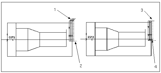
The following illustration shows the toolpaths for the various rough options:
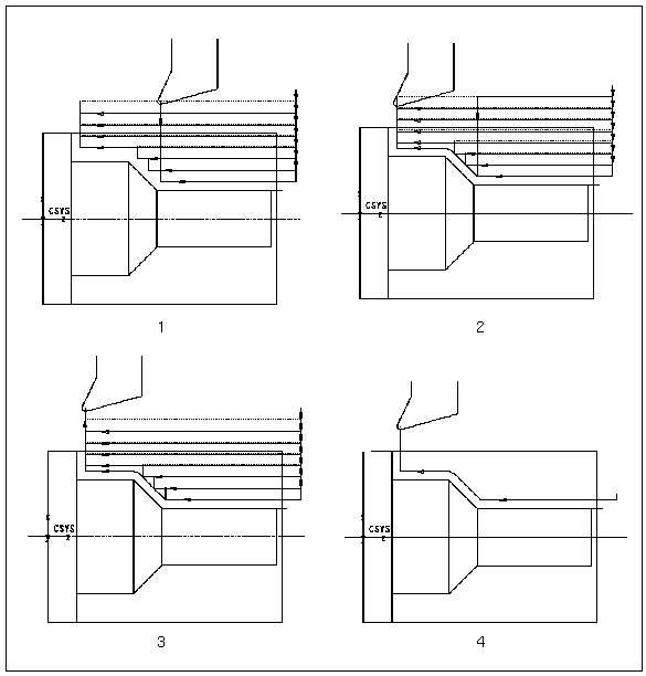
1. ROUGH_OPTION—ROUGH_ONLY
2. ROUGH_OPTION—ROUGH_&_PROF
3. ROUGH_OPTION—ROUGH_&_CLEAN_UP
4. ROUGH_OPTION—PROF_ONLY
TRIM_TO_WORKPIECE
Allows you to extend the tool path past the workpiece boundaries as sketched. If TRIM_TO_WORKPIECE is NO (the default), the machining zone will be formed by the whole sketch of the cut; the system will add a vertical line as the right boundary and a horizontal line as the left boundary. If TRIM_TO_WORKPIECE is set to YES, the machining zone will be defined on the outside by the workpiece boundaries, with a small extension past these boundaries determined by the Creo NC.
The following illustration shows the difference in toolpaths if you select the value for TRIM_TO_WORKPIECE as Yes and No respectively:
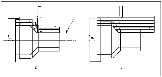
1. Section sketch extends past the workpiece.
2. TRIM_TO_WORKPIECE—YES
3. TRIM_TO_WORKPIECE—NO
CUT_DIRECTION
Allows you to reverse the default cutting direction for turning NC sequences (right-to-left for Outside and Inside turning, downward for Facing). The values are:
• STANDARD (default)—Use the default direction.
• REVERSE—Reverse the cut direction. The tool cuts left-to-right for Outside and Inside turning, and from the center upward for Facing.
OUTPUT_POINT
Allows you to choose which point of a left-handed tool is used as the control point for CL output:
• CENTER (default)—The center of the nose radius (the default control point).
• TIP—The output point is offset downwards and to the left from the default control point by the NOSE_RADIUS value.
• X_OFFSET—The output point is offset downwards from the default control point by the NOSE_RADIUS value.
• Z_OFFSET—The output point is offset to the left from the default control point by the NOSE_RADIUS value.
• CENTER_RIGHT—Same as CENTER, but on the right side of the tool (for Groove turning only).
• TIP_RIGHT—Same as TIP, but on the right side of the tool (for Groove turning only).
• X_OFFSET_RIGHT—Same as X_OFFSET, but on the right side of the tool (for Groove turning only).
• Z_OFFSET_RIGHT—Same as Z_OFFSET, but on the right side of the tool (for Groove turning only).
For a right-handed tool, the output point is offset to the right. Similarly, for a left-handed tool with a flashed tip, output point is offset to the right. |
All the offsets are determined with respect to the default tool section orientation. The same point is used for Outside, Inside, or Face turning. Applicable for Area, Profile, and Groove turning only.
The following illustration shows the exact point on the tool that is used if you select the value for OUTPUT_POINT as CENTER, TIP, X_OFFSET, and Z_OFFSET:
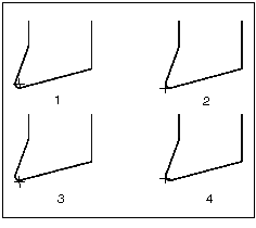
1. OUTPUT_POINT—CENTER
2. OUTPUT_POINT—TIP
3. OUTPUT_POINT—X_OFFSET
4. OUTPUT_POINT—Z_OFFSET
GOUGE_AVOID_TYPE
Allows you to specify the type of gouge checking for turning NC sequences. TIP_ONLY (the default) calculates gouge avoidance with respect to the tip of the tool only. TIP_&_SIDES calculates gouge avoidance with respect to the tip and both cutting sides of the tool. The tool path changes to avoid gouging, and material removal simulation reflects the tool geometry. Applicable for Area and Profile turning only.
The following illustration shows the toolpath and the workpiece after machining for both the GOUGE_AVOID_TYPE parameter values:
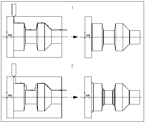
1. GOUGE_AVOID_TYPE—TIP_ONLY
2. GOUGE_AVOID_TYPE—TIP_&_SIDES
CORNER_FINISH_TYPE
Reflects the two ways of generating the tool path when passing a convex corner during a profiling pass of an Area NC Sequence:
• FILLET (default)—The tool path consists of two straight segments connected by an arc.
• STRAIGHT—The tool path consists of two straight segments extended until they intersect.
The following illustration shows the toolpaths that is generated if you select the value for CORNER_FINISH_TYPE parameter as FILLET or STRAIGHT:
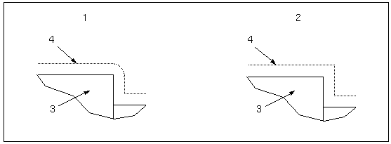
1. CORNER_FINISH_TYPE—FILLET
2. CORNER_FINISH_TYPE—STRAIGHT
3. Part
4. Tool path
STRAIGHT may not work if the tool size is too big to enter a cavity in the part. In the example in the\ following illustration, the tool (1) cannot completely enter the cavity in the part (2). If CORNER_FINISH_TYPE is FILLET, the system generates the tool path (3).\ If CORNER_FINISH_TYPE is STRAIGHT, the tool path cannot be generated (4). 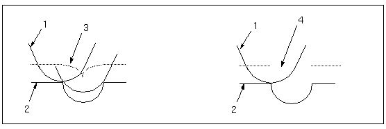 |
STEPOVER_ADJUST
YES (the default) allows you to uniformly distribute cutting passes across the area of the cut or along the groove width during a Rough NC sequence. If set to NO, the distance is determined by either STEP_DEPTH (for Area turning) or STEP_OVER (for Groove turning).
GROOVE_FINISH_TYPE
Allows you to specify an intermediate retract for the profiling pass of Groove turning NC sequences:
• NO_BACKCUT (the default)—The tool enters the groove on one side, retracts at some intermediate point along the groove profile, enters on the other side, and completes the cut.
• CONTINUOUS—The tool enters the groove on one side, cuts across, and exits on the other side.
ALTERNATE_SIDE_OUTPUT
If set to YES (the default is NO), allows you to generate CL output for Groove turning NC sequences based on the side of the tool cutting material. For scan types TYPE_1 and TYPE_1_CONNECT, the initial plunge is created with output point specified by the OUTPUT_POINT parameter. The tool retracts to the starting height. Creo NC then issues a new TURRET statement with OSETNO defined by the ALT_OSETNO_VAL parameter, and the tool moves to the beginning of the next plunge with the X, Y, Z output based on the side of the tool entering material. This pattern is repeated for all rough passes.
For profiling passes with GROOVE_FINISH_TYPE set to NO_BACKCUT, the first output point, specified by the OUTPUT_POINT parameter, is active until the retract that occurs at the intermediate point along the groove. Once the tool returns to starting height, Creo NC issues a new TURRET statement with OSETNO defined by the ALT_OSETNO_VAL parameter, and the rest of the groove is cut with the other side of the tool and the new offset register.
DEEP_GROOVE_OPTION
Provides two options for machining deep grooves:
• BY_DEPTH (the default)—The tool cuts to the bottom of the groove in PECK_DEPTH increments, retracting at FULL_RETRACT_DEPTH, if specified, before stepping over to the next pass.
• BY_WIDTH—The tool completely machines the whole width of the groove at each PECK_DEPTH.
Applicable for Groove turning NC sequences only.
STEP_DEPTH_COMPUTATION
Provides two options to compute the step depth:
• BY_REGION—The step depth is calculated based on the region. The tool cuts the specified depth based on the values specified for the STEP_DEPTH, STEPOVER_ADJUST, MIN_STEP_DEPTH, and NUMBER_PASSES parameters. The tool then cuts the remaining material in one pass if the cut depth is greater than or equal to the specified MIN_STEP_DEPTH within the region.
• BY_AREA—The step depth is calculated based on the area. In this case, the toolpath has a constant step depth. The last pass may or may not have a different step depth depending on the amount of material remaining to be removed.
Cut Param
TOOL_CLEARANCE
The distance used to degouge the tool holder when solid tool outline is used.
STEP_DEPTH
The incremental depth of each pass during rough cut NC sequences. The STEP_DEPTH must be greater than zero. The default is not set (displayed as "–1"). Applicable for Area turning only.
END_STEP_DEPTH
If the values of END_STEP_DEPTH and STEP_DEPTH are different, then the step depth of the NC sequence starts at the value of STEP_DEPTH and gradually increases or decreases with each additional slice until the final slice. At the final slice the value of the STEP_DEPTH is the same as the END_STEP_DEPTH value. Applicable for Area turning only.
MIN_STEP_DEPTH
Controls how the intermediate reference part diameters are machined. The default is a dash (-), which means that all diameters will be machined to stock allowance. Applicable for Area turning only.
ROUGH_STOCK_ALLOW
and
PROF_STOCK_ALLOW
The amount of stock left after the rough cut for the finish cut. Both parameters are used for Rough Cut NC sequences only, and specify different stock allowances for roughing and profiling cuts in Area and Groove NC sequences. PROF_STOCK_ALLOW must be set to a value less than or equal to ROUGH_STOCK_ALLOW. When geometry is displayed after automatic material removal, Creo NC uses PROF_STOCK_ALLOW. The default value for PROF_STOCK_ALLOW is 0.
In the following illustration, the schematic on the left shows the tool path for ROUGH_OPTION set to ROUGH_ONLY. The amount of stock left after the last cut is equal to ROUGH_STOCK_ALLOW (1). If ROUGH_OPTION is ROUGH_&_PROF, as shown in the schematic on the right, the tool will also make a profiling pass (2), with the amount of stock left after this cut equal to PROF_STOCK_ALLOW (3).
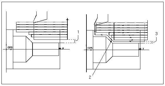
STOCK_ALLOW
Determines the stock allowance for Profile turning NC sequences and final programmed thread depth for Thread turning. The default is 0.
Z_STOCK_ALLOW
Specifies the stock allowance in the Z direction, enabling you to leave different amounts of stock on the diameters and faces of a workpiece. This parameter is implemented for Rough turning only. The default value is a dash (-), in which case the ROUGH_STOCK_ALLOW value is used.
Step Depth and Stock Allowance
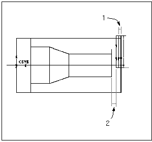
1. STEP_DEPTH
2. Z_STOCK_ALLOW (or ROUGH_STOCK_ALLOW if Z_STOCK_ALLOW is "-")
NUMBER_PASSES
Gives you additional control over the number of tool passes during an Area or Groove NC sequence (also controlled by the STEP_DEPTH parameter for Area turning, or STEP_OVER for Groove turning). Creo NC computes step depth using the NUMBER_PASSES parameter value (if other than 0), compares it with the STEP_DEPTH (or STEP_OVER) value, and uses the lesser value.
CUT_ANGLE
Allows you to cut at an angle. For Outside and Inside turning the angle is measured with respect to the Z axis, for Facing—with respect to the X axis. The default is 0. Applicable for Area turning only. The following illustration shows the tool path if CUT_ANGLE (1) is set to 165 degrees.
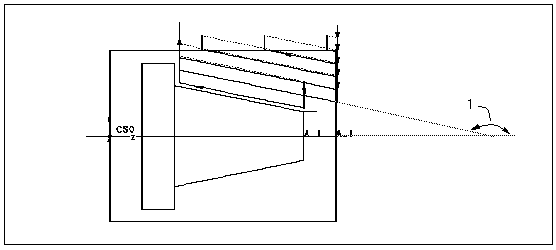
NUM_PROF_PASSES
Specifies the amount of profiling passes. Applicable for Area and Groove turning when ROUGH_OPTION is ROUGH_&_PROF or PROF_ONLY. The default is 1.
PROF_INCREMENT
Specifies the offset between the profiling passes. The final pass is always the same, which means that the first pass is offset from the final pass by: (NUM_PROF_PASSES–1)*PROF_INCREMENT. The default value for PROF_INCREMENT is 0. If NUM_PROF_PASSES is greater than 1, you must specify a positive value for PROF_INCREMENT.
In the example in the following illustration, NUM_PROF_PASSES is 3. The tool makes three cutting passes, offset from each other by the PROF_INCREMENT value (1).
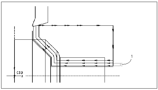
CONCAVE_RADIUS
Defines the radius for a Round corner condition at a concave corner.
CONVEX_RADIUS
Defines the radius for a Round corner condition at a convex corner.
CHAMFER_DIM
Defines the size of the chamfer when a Chamfer corner condition is added.
START_OVERTRAVEL
and
END_OVERTRAVEL
These two parameters specify the distance that the tool travels outside the workpiece in the beginning and the end of each pass, respectively. Applicable for Area and Profile turning. The default value is 0. For Area turning, START_OVERTRAVEL and END_OVERTRAVEL are applied only if the cut extension is parallel to the direction of the cut motion, as shown in the following illustration, where START_OVERTRAVEL is applied (1), while END_OVERTRAVEL is not applied (2).
BACK_CLEAR_ANGLE
The minimum angle by which the back end of the tool clears the workpiece as it enters an area of smaller diameter than was previously being machined. The default is 5.
STEP_OVER
The distance between two neighboring cuts. The default is not set (displayed as "–1"). Applicable for rough Groove turning (that is, with ROUGH_OPTION other than PROF_ONLY).
SIDEWALL_OFFSET
Allows you to control the intermediate retract point for the profiling pass in Groove turning (when ROUGH_OPTION is PROF_ONLY or ROUGH_&_PROF, and GROOVE_FINISH_TYPE is NO_BACKCUT). SIDEWALL_OFFSET specifies the length of the second portion of the cut, that is, the distance between the point of retract and the end of the bottom of the groove. The default is a dash (-), in which case the tool retracts at the midpoint of the bottom entity.
PECK_DEPTH
If set to a value other than 0, the peck cycle is performed. The default is 0. Applicable only for rough Groove turning (that is, with ROUGH_OPTION other than PROF_ONLY).
ALT_OSETNO_VAL
Specifies the alternative offset register value for Groove turning NC sequences when the ALTERNATE_SIDE_OUTPUT parameter is set to YES. The default value is a dash (-), that is, not used.
CONNECT_OVERLAP
Specifies the distance that the tool travels along the surface of the part after a pass, before profiling to the start point of the next pass. The CONNECT_OVERLAP parameter is used only if the SCAN_TYPE is specified as TYPE_1_CONNECT.
END_CUT_FEED
Generally, when a turning tool is approaching a shoulder, there may be some stress on the cutting edge of the tool due to a sudden change in the turn. To avoid this stress, you can set the feed rate of the cut motion by specifying an appropriate value for the END_CUT_FEED parameter.
CUT_FEED_CLEAR
Specifies the distance from the shoulder at which the cut feed specified in the END_CUT_FEED parameter is applied.
Machine
SWISS_TURN
If set to YES, and if the machine has Swiss-type turning capability, theMODE / ZAXIS, ON statement is output in the CL data for each sequence. This parameter is available in area turning, profile turning, groove turning, 4-axis area turning, and thread turning steps. The default is NO. If the machine does not the Swiss-type turning capability or if this parameter is set to NO, there is no change in the CL data.
SPINDLE_SPEED
The rate at which the machine spindle rotates (RPM). The default SPINDLE_SPEED is not set (displayed as "–1").
SPINDLE_SENSE
The direction of spindle rotation. CW (clockwise—default), CCW (counterclockwise).
SPINDLE_RANGE
NO_RANGE (default), LOW, MEDIUM, HIGH, NUMBER. If a value other than NO_RANGE is set, range is included in the SPINDL command in the CL file (for example, "RANGE, LOW"). If set to NUMBER, the RANGE_NUMBER parameter value is used in the SPINDL command (for example, "RANGE, 4", where 4 is the RANGE_NUMBER parameter value).
RANGE_NUMBER
The value you specify is used as the RANGE_NUMBER in the SPINDL command if SPINDLE_RANGE is set to NUMBER. The default is 0.
MAX_SPINDLE_RPM
If set to a value other than a dash (-) (which is the default), the MAXRPM attribute is added to the SPINDL command.
SPEED_CONTROL
CONST_RPM (constant revolutions per minute), CONST_SFM (constant surface feet per minute), CONST_SMM (constant surface meters per minute).
The default SPEED_CONTROL is CONST_RPM.
CUTCOM
Controls tool compensation. The options are:
• ON—Turns on the tool compensation in the CL file.
• OFF (the default)—No tool compensation provided.
CUTCOM statements are not output for cut motions.
CUTCOM_REGISTER
Specifies the number of the register of the machine controller that holds the tool compensation data. The default is 0.
TOOL_ORIENTATION
Allows you to control the tool orientation. It represents the angle (in degrees) from the tool axis clockwise to the Z-axis of the NC Sequence coordinate system. TOOL_ORIENTATION can be any value between 0 and 360. The default is 0.
For Head 2, the angle is measured counterclockwise. That is, if TOOL_ORIENTATION is 90, for Head 1 the tool shank is oriented along the positive X-axis of the NC Sequence coordinate system, while for Head 2 the tool shank is along the negative X-axis. |
TOOL_POSITION_ANGLE
Allows you to position a turning tool by rotating it by a fixed angle about the Y-axis. TOOL_POSITION_ANGLE can have any value from 0 to 360. The default is 0.
For example, if you set the value of TOOL_POSITION_ANGLE to 15 and set Rotation to Standard in the Tools Setup dialog box, then the output in the CL file is ROTHED/BAXIS, ATANGL, 15.00, CCW.
• To apply the TOOL_POSITION_ANGLE parameter, turning tool positioning must be enabled in the Mill/Turn workcell • The value that you specify for TOOL_POSITION_ANGLE is added to the value of TOOL_ORIENTATION to set the cutting orientation of the tool. |
A positive value for TOOL_POSTION_ANGLE rotates the tool in the counterclockwise direction about the Y-axis while a negative value rotates the tool in the clockwise direction about the Y-axis. Positive and negative values indicate the rotation sense assigned in the workcell.
FLASH_TOOL
Allows you to flash a cutting tool, that is, rotate the tool by 180 degrees in its spindle to cut in the opposite direction. Set FLASH_TOOL to YES to enable flashing of the tool. The default is NO.
If you set FLASH_TOOL to YES for a tool with a flashed orientation, the tool orientation is rotated about the X-axis by 180 degrees and the cutting direction is reversed. If you set FLASH_TOOL to YES for a tool that does not have a flashed orientation, a message appears stating that you have not defined a flashed orientation for the tool.
If FLASH_TOOL is set to YES, then the TURRET statement in the CL file displays the offset register. This is the offset number defined for a Flashed orientation in the Offset Table tabbed page of the Tools Setup dialog box.
DELAY
The duration in seconds of a period of tool dwelling at the bottom of the groove. The default is 0, in which case the "DELAY / t" statement is not used in the CL file. Applicable for Groove turning only.
Entry/Exit
PLUNGE_ANGLE
The angle at which the tool approaches the workpiece. The default is 0. Applicable for Area and Profile turning.
PULLOUT_ANGLE
The angle at which the tool is pulled away from the workpiece. The default is 0. Applicable for Area and Profile turning.
The following illustration shows the toolpath representation for different PULLOUT_ANGLE values:
1. PLUNGE_ANGLE 45
2. PULLOUT_ANGLE
3. PLUNGE_ANGLE 0
4. PULLOUT_ANGLE 45
RETRACT_RATIO
Controls the depth of the tool retracting motion during an Area turning NC sequence. This depth is specified as a ratio of STEP_DEPTH. The default is 1.1.
The following illustration shows the usage of RETRACT RATIO in Area turning NC sequences:
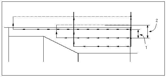
1. STEP_DEPTH
2. Retracting depth = STEP_DEPTH * RETRACT_RATIO
PULLOUT_DIST
Used for the final retract of the tool. The default is 0, in which case the system default value for retract is used. Applicable for Groove turning only.
FULL_RETRACT_DEPTH
Applicable for peck cycle Groove turning only. If other than 0 (the default), the tool retracts all the way back to CLEAR_DIST upon reaching this depth below the top of the groove.
CLEAR_DIST
For Groove NC sequences, the clearance distance above the workpiece surface at which the PLUNGE_FEED ends and the CUT_FEED begins. For Thread NC sequences, the clearance distance from the workpiece (corresponds to "d" in the AI parameter "FEDTO, d"). The default is 1.
APPROACH_DISTANCE
In Area turning, used for the initial entry into rough turning, as well as for the entry into the profiling motion. Also specifies the length of approach Tool Motions for all NC sequence types. The default is 0.
EXIT_DISTANCE
In Area turning, used for the final exit from rough turning, as well as for the exit from the profiling motion. Also specifies the length of exit Tool Motions for all NC sequence types. The default is a dash (-), that is, 0.
LEAD_RADIUS
The radius of the tangential circular movement of the tool when leading in or out. Used when creating Lead In and Lead Out Tool Motions, and in Build Cut for Profile turning. The default is 0.
TANGENT_LEAD_STEP
The length of the linear movement that is tangent to the circular lead-in or lead-out motion. Used when creating Lead In and Lead Out motions in Build Cut for Profile turning. The default is 0.
NORMAL_LEAD_STEP
The length of the linear movement that is normal to the tangent portion of the lead-in or lead-out motion. Used when creating Lead In and Lead Out motions in Build Cut for Profile turning. The default is 0.
CUT_ENTRY_EXT
For Profile Turning, specifies the entry move type for individual cuts or slices. It has the following values:
• NONE—No entry move.
• LINE_TANGENT—The tool enters in a line tangent to the cut or slice.
• NORMAL—The entry motion is a straight line normal to the cut motion.
• LEAD_IN—The tool leads into the cut or slice.
• PLUNGE—The tool plunges before a selected cut motion or approach motion. This parameter works in conjunction with the APPROACH_DISTANCE and PLUNGE_ANGLE parameters.
CUT_EXIT_EXT
For Profile Turning, specifies the default exit move type for intermediate cuts or slices. It has the following values:
• NONE—No exit move.
• LINE_TANGENT—The tool exits in a line tangent to the cut or slice.
• NORMAL—The exit motion is a straight line normal to the cut motion.
• LEAD_OUT—The tool exits along an arc to the cut or slice.
• GOTO_END—The tool moves to the specified datum point at the end of the cut motion if you specify an end point while defining a Profile turning step. The direction in which the tool moves is defined when you select the option of the END_MOTION parameter.
• GOHOME—The tool moves to the specified Home point at the end of the cut motion. You must have specified a Home point for the operation. The direction in which the tool moves is defined when you select the option of the END_MOTION parameter.
• PULLOUT—The tool moves away after a selected cut motion. This parameter works in conjunction with the EXIT_DISTANCE and PULLOUT_ANGLE parameters.
ENTRY_ANGLE
The angle of the arc created by the circular movement of the tool when leading in. Used when creating Lead In and Lead Out motions in Build Cut for Profile turning. The default is 90.
EXIT_ANGLE
The angle of the arc created by the circular movement of the tool when leading out. Used when creating Lead In and Lead Out motions in Build Cut for Profile turning. The default is 90.
The following illustration shows the various entry/exit parameters used in Profile turning:
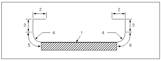
1. cut motion
2. NORMAL_LEAD_STEP
3. TANGENT_LEAD_STEP
4. LEAD_RADIUS
5. ENTRY_ANGLE
6. EXIT_ANGLE
Thread
THREAD_FEED
Number of threads per inch. The default value is not set (displayed as "–1").
THREAD_FEED_UNITS
TPI (default), MMPR, IPR. Allows alternate pitch designations.
PERCENT_DEPTH
A decimal number between 0 and 1 that indicates the percentage of remaining material to be removed with each pass.
This option is valid only for AI macros, not for ISO standard CL Data. |
NUMBER_FIN_PASSES
Sets the number of passes to be made after the final thread depth (determined by STOCK_ALLOW) is reached. The default is 1.
NUMBER_STARTS
The number of threading starts in multiple start threading (corresponds to the AI parameter "TIMES,t" and to the ISO parameter "MULTRD,t"). For example, if NUMBER_STARTS is set to 4, then four threading starts are spaced at equal intervals around the part.
NUMBER_CUTS
For ISO threads, the number of times the tool will be positioned to a multiple cut (corresponds to the ISO parameter "CUTS,c").
NUM_TRANSVERSE_CUTS
For AI threads, the number of times the tool will be positioned to a multiple cut (corresponds to "n" in the AI parameter "OFSETL,n,o").
CUT_OFFSET
For AI threads, the offset distance between the cuts in multiple cut threading (corresponds to "o" in the AI parameter "OFSETL,n,o").
The following illustration shows the NUM_TRANSVERSE_CUTS and CUT_OFFSET parameters. In this example, NUM_TRANSVERSE_CUTS equals 4.
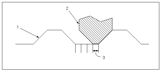
1. thread profile
2. tool
3. CUT_OFFSET
OUTPUT_THRD_PNTS
If set to YES (the default), uses GOTO statements for the first and last points of the thread into the CL file, before and after the THREAD/AUTO command, respectively. If set to NO, does not use these GOTO statements.
INFEED_ANGLE
Angle at which the tool begins the cut. The default value is 0.
THREAD_DEPTH
Thread depth (for General thread type only). The default value is not set (displayed as "–1").
THREAD_DEPTH_METHOD
This parameter provides the following methods to determine the final thread depth:
• BY_STEP—Specifies the incremental depth for each cut. This is the distance the tool moves with each pass.
• BY_PERCENT—Specifies that a percentage of material is removed with each successive pass. Specify this percentage using the PERCENT_DEPTH parameter.
• BY_CUTS—Enables you to specify the total number of cuts for the tool to reach the final thread depth.Enter the value using the NUMBER_CUTS parameter.
• FULL_DEPTH—Specifies that a single pass is made to reach the final thread depth. This is the default method.
General
MATREMCUT_INBOUND—If set to YES, creates an accurate material removal cut for an internal diameter turn profile. Applicable for Profile turning only.