HMX Configuration Options
The customization of HMX has now been moved to a new tab in the HMX window. These customizations are only available while using an HMX Advanced license. The customizations appear under several sections, as detailed below:
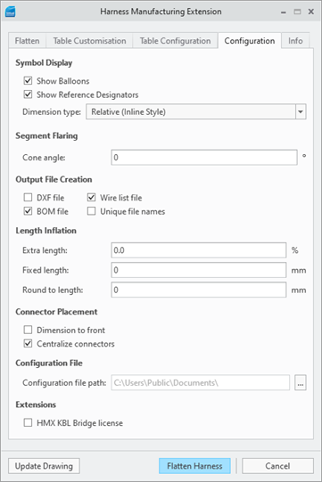
Symbol Display
This section controls the showing or hiding of balloons and reference designator labels in the drawing that HMX generates. The choices for these options are Show or Hide.
If the option Show Balloons is deselected, the BoM balloons layers are hidden in the generated drawing.
If the option Show Reference Designators is deselected, the reference designator labels are hidden in the generated drawing.
By default, these options are selected.
Both the BoM balloons and the Ref_Des labels are visible. 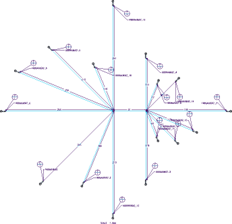 | The BoM balloons layer is visible, but the Ref_Des labels layer is hidden.  | Both the BoM balloons layer and the Ref_Des labels layer are hidden. 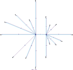 |
This section also controls the dimension type. The possible choices are Relative (Inline Style), Relative (Leader Style), Absolute (Inline Style), Absolute (Ordinate Style), or None.
Relative Leader Dimensioning
The segments on the 2D drawing can have either Relative Inline dimensions or Relative Leader dimensions applied. This is purely a cosmetic change, see the next figure, and the value of the dimension is unchanged. Select the type of dimension from the Configuration tab in the Symbol Display section.
Relative Inline Dimensions 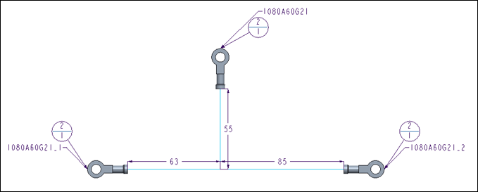 | Relative Leader Dimensions 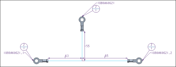 |
Absolute Dimensioning
This functionality is available only with an Advanced HMX license. The two options for absolute dimensioning are Absolute (Inline Style) or Absolute (Ordinate Style). Absolute dimensions calculate lengths based on the start connector, that is the left-most connector on the main branch. Absolute dimensioning is applied only along the main branch. All other segments will be dimensioned using the style of the inline dimensions.
Absolute Inline Dimensions  | Absolute Ordinate Dimensions  |
No Dimensioning
In HMX V51 you can create an HMX drawing with no dimensions. This functionality is available only with an Advanced HMX license.
Segment Flaring
This section controls the angle from the horizontal or vertical direction from which the first segment in a group of splayed segments is placed.
Cone angle 15 degrees | Cone angle 30 degrees |
|---|---|
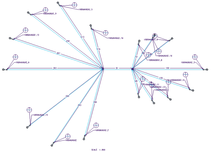 | 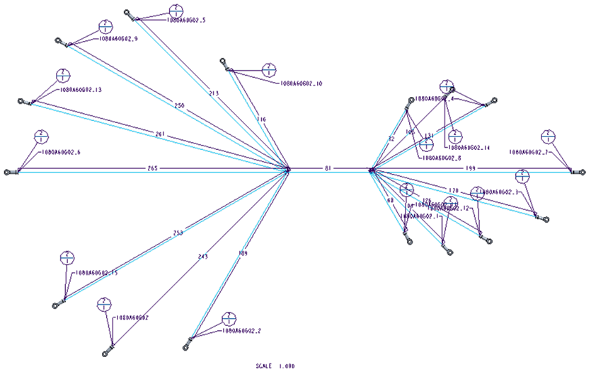 |
The value for this is a natural number (no decimals).
Values over 75 trigger a warning, indicating that the output in the drawing file may appear to have overlapping segments, and may be unreadable.
The default value is 0, indicating that the first segment is placed horizontally from the trunk.
The maximum value is 89, indicating that all wires in a splay are constrained within 1 degree from either side of the main branch.
File Creation
This section controls the generation of files from HMX.
You can select the following options:
• DXF File— If this option is selected and if you have the HMX Advanced License, the HMX_Log.txt file is generated, which is a Drawing Exchange Format file. By default, this option is not selected.
• BoM File— If this option is selected and if you have the HMX Advanced License, the HMX_BOM.csv file is created with the contents of the BoM table present in the drawing. By default, this option is not selected.
• Wirelist file — If this option is selected and if you have the HMX Advanced or HMX Standard license, the the HMX_WireList.csv file is created, with the contents of the Wire List table present in the drawing. By default, this option is not selected.
• Unique File Names — Controls whether the generated files have unique names. If this option is selected, every file created by HMX has a unique name, including the date and time when HMX was run. If this option is not selected, the files from previous runs of HMX are overwritten, unless you have renamed them. By default, this option is not selected.
Length Inflation
This section controls the values of the wires and cables lengths output to the Wire List and BoM. These values are only reflected in the Wire List and the BoM tables but not in the generated stick drawing. The generation of the Wire List and BoM tables are restricted by the presence of a Standard and/or Advanced HMX license.
The option Extra Length (%) sets an additional percentage of length to each cable in the Wire List and to the owner spool in the BoM.
The acceptable values for this option are real numbers between 0 and 85070586659632214952926045871129231360.
The value input into the text input panel is restricted to 3 decimals, for example, 5.125, indicating that the cable length is inflated by 5.125%.
The default value is 0, indicating that no wire inflation is applied.
The option Fixed Length controls the amount of cable to add to each item in the Wire List. The type of value for this option is dictated by the unit used by the harness . If the harness is in millimeters, the value will be restricted to a natural number (no decimals). For example, if 10.5 is entered into the input panel, the value is changed to 10 by HMX.
If the harness is in inches, the value is restricted to real numbers with up to 1 decimals. For example if the value 10.55 is entered into the input panel, the value is changed to 10.5 by HMX.
The minimum value for this option is 0. The maximum value is dictated by the harness unit. For real numbers, the maximum value is 85070586659632214952926045871129231360.0.For natural numbers, the maximum is 2147483647.
The default value is 0, indicating that no wire inflation is applied.
The options Fixed Length and Extra Length (%) are mutually exclusive. If both options are given values, the percentage length is ignored, and only the fixed length value is taken into consideration. |
The option Round to Length controls the value for wires and cables. The type of value for this option is dictated by the harness unit.
If the harness is in millimeters, the value is restricted to a natural number (no decimals).For example, if 10.5 is entered into the input panel, the value is changed to 10 by HMX.
If the harness is in inches, the value is restricted to real numbers with up to 1 decimals.For example, if the value 10.55 is entered into the input panel, the value is changed to 10.5 by HMX.
The minimum value for this option is 0. The maximum value is dictated by the harness unit. For real numbers, the maximum value is 85070586659632214952926045871129231360.0. For natural numbers, the maximum is 2147483647.
The default value is 0, indicating that the default rounding up to the nearest natural number is applied for harnesses in millimeters, and no rounding is applied to harnesses in inches.
Connector Placement
This section controls the placement of connectors in the sketch present in the drawings generated by HMX.
The option Dimension to Front controls the dimensioning scheme used by HMX. This option is only available alongside the HMX Advanced license.
If this option is selected, the dimension placed on the segment leading to the connector on the sketch contains the length of the connector, and appears to go to the full length of the connector.
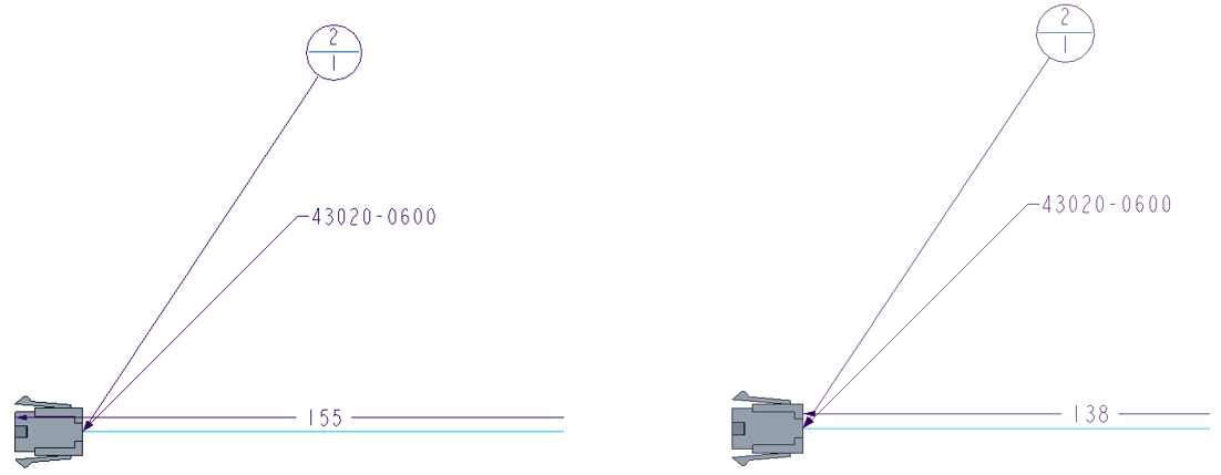
If this option is not selected, the dimension placed on the segment leading to the connector stops at the end of the connector, and does not include the connector length.
By default, this option is unchecked.
The Centralize Connectors controls the attachment of the connector to the segment leading to it.
If this option is selected, the connector is attached to the sketch from a pin which is in the center of all the routed pins.
If this option is not selected, the connector is attached to the sketch by the pin corresponding to the shortest length entering the connector.
By default, this option is unchecked.
Configuration File
This section controls the location of the configuration file that is used by HMX. The option Configuration file location allows you to select a folder from which an HMX configuration file can be read. This configuration file stores the options selected by you and applies them to the current session. After selecting a new configuration file location, the HMX user interface must be closed and reopened to apply the changes. The default value for this option is the Creo Parametric working directory.
Custom Configuration File Location
HMX V50+ enables you to define a custom path to the location of an HMX configuration file. By default, HMX applies the configuration file found in the Creo Parametric working directory. This functionality enables you to select a different configuration file location without altering the working directory.
To select a different configuration file location:
1. Navigate to the Configuration panel of the HMX user interface.
2. At the Configuration File section, click the three dots, as highlighted in the figure below.

3. Navigate to the custom location and select Open.
4. The new custom path will appear in the HMX user interface.
5. Close the HMX user interface and restart Creo Parametric to apply changes.
Any changes to the configuration file location are retained through subsequent sessions of HMX and Creo Parametric.
The working directory remains unchanged.
This file must be named hmx_config.hmx.
Extensions
This section controls HMX Extensions.
The option HMX KBL Bridge License checks out a license to use the HMX KBL Bridge (HKB) product. This product creates a KBL file representing the HMX created drawing. A license for HKB can be obtained by contacting Virtual Interconnect.
By default, this option is unchecked, and no license will be checked out.