Example Run
Using the supplied backshell_model.asm with the Backshell_model folder, the following section details an example of using Table Customisation and Table Configuration to create a customs table for the backshell_model.asm.
Creation of Tables
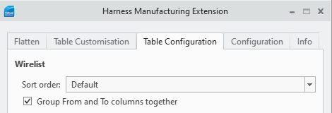
Open HMX and select the Table Customisation panel. To create a custom Wirelist table, select four Wire/Cable parameters from the drop-down menu: NAME, SPOOL, LENGTH and REF_DES. Because the REF_DES parameter has multiple values, from and to, the Table Customisation panel automatically creates two columns. Ensure that the Group From and To columns together option is selected.
The result of the Wirelist table is shown below.
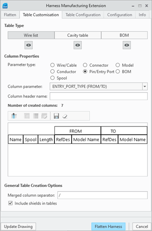
The above figure shows the default wirelist table:
• The NAME parameter column with a header name Name.
• The SPOOL parameter column with a header name Spool.
• The LENGTH parameter column with a header name Length, and two pairs of directional columns: connector REF_DES columns with a header name RefDes and connector MODEL_NAME columns with a header name Model Name.
Clicking Save table saves the created table to the tables.hmx file. The same process is followed to create the custom Cavity and BOM tables. Previews of these tables are given in figure below.
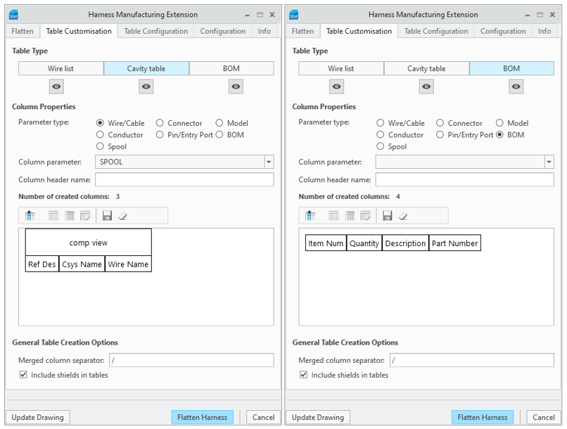
To create the cavity table the Connector REF_DES, Pin/Entry Port ENTRY_PORT CSYS_NAME and Wire/Cable NAME parameters were chosen from the dropdown menu. For the BOM table parameters, ITEM NO, QUANTITY, DESCRIPTION and PART NUMBER were chosen.
When a column has been created for a parameter, that parameter is removed from the drop-down menu. This is to avoid a duplicate column in the tables. |
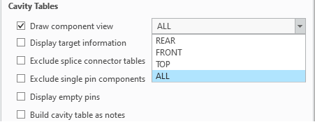
On the Table Configuration panel, under Cavity Tables, ensure the Draw component view checkbox is selected, and select ALL from the dropdown menu. This displays all views of the connector in the Cavity table.
Custom Table Output
After each table is saved, click Flatten Harness. HMX extracts the custom tables and produces them within the drawing. The first row of a custom Wirelist table contains the column header values specified when creating the table. After that, each row contains the corresponding values for each of the parameters for every wire in the harness. For example the figure below shows the output of the custom Wirelist created in the previous section. Note that for Wire/Cable LENGTH parameter column, the units of wire lengths are added to the column header.

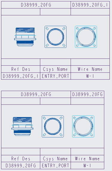
For custom cavity tables, if the component view is selected, the first row contains the model name and Ref Des followed by the view of the component. On the fifth row of the header, the names are listed. After that, every row contains the values of each parameter. The figure below shows the cavity table created for each connector using the example from the previous section.
As with the default BOM tables, the custom BOM tables are created in reverse. That is, column headers are on the bottom row in BOM tables. Thus, every row above the column headers corresponds to the values of the selected parameters used to create the table. The figure below shows the BOM table produced from the custom table that was created in the previous section.
