About Automatic UDFs
Use Automatic UDFs to define features in connecting parts. Creating Automatic UDFs is a two-step process:
1. On the ribbon, click >  Definition operations >
  New AutoUDF definition. The AutoUDF Definition dialog box opens, where you can add an Automatic UDF definition to a coordinate system.
Definition operations > New AutoUDF definition. The AutoUDF Definition dialog box opens, where you can add an Automatic UDF definition to a coordinate system.2. After you assemble a part or assembly containing an AutoUDF Definition several times, use the  Manage AutoUDFs dialog box to create all the holes and cutouts, that you already defined, in the attaching parts.
Manage AutoUDFs dialog box to create all the holes and cutouts, that you already defined, in the attaching parts.Use case
The following example is a typical Automatic UDF use case, where a plate uses the same hole pattern as another part in the assembly:
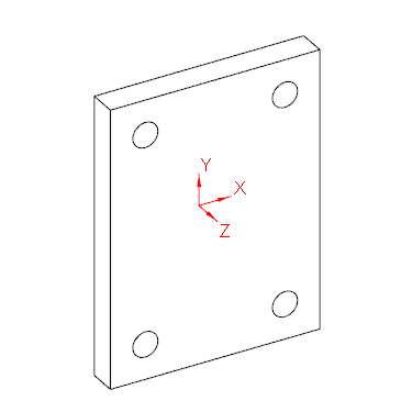
1. You can add an Automatic UDF definition of the hole pattern on the plate’s coordinate system, as pictured below:
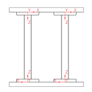
2. After you assemble this plate several times, you can also create holes in the two horizontal beams that touch the plates. On the ribbon, click > Definition operations > New AutoUDF definition. The AutoUDF Definition dialog box opens, where you can add an Automatic UDF definition to the plates’ coordinate system.
Definition operations > New AutoUDF definition. The AutoUDF Definition dialog box opens, where you can add an Automatic UDF definition to the plates’ coordinate system.As pictured below, the XY-plane of the plates’ coordinate system must touch the two horizontal beams for you to create holes in them. Note that the Z-axis is mirrored on the top and bottom plates in order to face away from the two horizontal beams, as Automatic UDFs are always created on the negative Z-axis.
3. On the ribbon, click > > to create the holes that you defined in the horizontal beams.

Creating Automatic UDFs
You can create an Automatic UDF in the following ways:
• On the ribbon, click > .
• To use Automatic UDF functionality with non-standard end plate connectors and the default setting for a hole pattern, in the Element Definition dialog box, select Auto UDF holes.Then enter values for hole depth, UDF_T.
• Include Automatic UDF definitions for holes in parts that touch a point pattern profile. Use the Point Pattern command to define a point pattern, then select the With automatic UDF attachment hole check box. Enter a value for the attach hole depth in the T box.
• Define a screw connection using Creo Intelligent Fastener. In the Screw Fastener Definition dialog box, select the Side 1 — Auto UDF check box or the Side 2 — Auto UDF check box, then type an offset value.
You can manage the creation of UDFs in attaching parts. On the ribbon, click > > . The Manage AutoUDFs dialog box opens, where you can create, update, suppress, resume, delete, and check the status of Automatic UDFs you create.
Manage AutoUDFs dialog box opens, where you can create, update, suppress, resume, delete, and check the status of Automatic UDFs you create.