Common Parameters
Parameters common for all types of measure steps are listed below. They are listed under a heading corresponding to the category, or branch, in the Edit Parameters dialog box that you use to set up the parameters.
|
|
• You must supply a value for all parameters that have a default of "-1".
• Some parameters may have a value of dash (-), that is, "ignore". This means that this parameter is optional, and if you do not supply a value for it, it will not be used. For some parameters, the system will use a certain default value, or a value of another parameter, instead. The dash (-) value is only acceptable for those parameters that have it as a default.
• Length units for step parameters (where applicable) are the same as the CMM assembly units. If the assembly units are changed using the Same Size option (so that the dimension values are changed), all the appropriate parameters of the currently existing measure steps will also be scaled.
|
Feed
MEASURE_FEED
The rate at which the probe moves when performing measurements. The default is "-1".
SAFE_FEED
The rate at which probe moves at a safe distance above the level of the part (e.g., between a Pull Out Point and the next Approach point). The default is "-1".
MEASURE_ACCEL
Defines the acceleration in measure mode. The default is "-1".
SAFE_ACCEL
Defines the acceleration when moving at a safe distance above the level of the part. The default is "-1".
ACCEL_UNITS
Units for the acceleration rates above. The values are: IPMM (inches per minute per minute—default), MPMM (meters per minute per minute), PCENT (percent of maximum value).
FEED_UNITS
Units for the feed rates above. The values are: IPM (inches per minute—default), MPM (meters per minute), PCENT (percent of maximum value).
Meas Params
These parameters depend on the type of Measure step. See the Specific Parameters section in the reference help topic for the appropriate step type.
Machine
PROBE_COMPENSATION
Specifies if the probe compensation is ON or OFF. The default is OFF.
Entry/Exit
PULLOUT_DIST
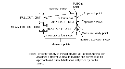
Specifies the length of pullout moves, i.e., the distance between the Measure Ready point and the Pull Out point. The default is a dash (-), in which case the MEAS_PULLOUT_DIST value will be used instead.
APPROACH_DISTANCE
Specifies the length of approach moves, i.e., the distance between the Approach point and the Measure Ready point. The default is a dash (-), in which case the MEAS_APPR_DIST value will be used instead.
BORDER_CLEARANCE
Specifies the distance from the borders of geometry being measured (such as plane, surface) where no measure points should be located. If a Measured point falls within this clearance, it will be ignored. The default is a dash (-), that is, 0.
MEAS_APPR_DIST
Defines the length of the measure approach move, i.e., the distance between the Measure Ready point and the Measured point. The default is "-1".
MEAS_PULLOUT_DIST
Defines the length of the measure pullout move, i.e., the distance that the probe pulls out (at slow speed) after measuring a point. The default is "-1".
MEAS_SEARCH_DIST
Defines the length of the measure search move, for example, the distance that the probe continues to measure beyond the MEAS_APPR_DIST distance to try and make contact with and record a value for the item being inspected.
Default Probe Path Based on Parameter Values

Scan
MIN_NUMBER_PTS
Specifies the minimum number of measure points required in a segment.
MEAS_LIN_TOL
Specifies linear tolerance for scan.
MEAS_ANG_TOL
Specifies angular tolerance for scan.
MEAS_MAX_DIST_BTWN_PNTS
Specifies the maximum allowable distance between measure points the segments.
MEAS_SCAN_DIST_FROM_START_PNT
Defines the start point when removing a set of measure points from an acquisition segment. Specifies the offset between start point of the segment and the first point to be removed.
MEAS_SCAN_DIST_FROM_END_PNT
Defines the end point when removing a set of measure points from an acquisition segment. Specifies the offset between end point of the segment and the last point to be removed.
Vision
SEARCH_WINDOW_SIZE
Defines a window to limit the field of view for the camera probe. The value can be from 0.01 to 1.
LIGHT
Defines the lighting for taking measurements with the camera probe. The values are SURF (normal reflected light—default), BACK (projected light), GRID (artificial contrast projection for automatic focusing), OBLQ (oblique, reflected light), STROBE (strobe lighting and image acquisition).
FILTERS
Defines a filter for use with the video measuring equipment.
ALGORITHMS
Specifies video measurement algorithms.
MAGNITUDE
Specifies the magnification of the lens.
APERTURE
Specifies the aperture setting.