About Defining Diagram Symbols
Components and fixed (non-parametric) connectors in Diagram are represented by drawn symbols. Symbols can be defined and saved in both Drawing and in Diagram mode. When you place a symbol in the drawing, you place an instance of the symbol based on a definition that has already been created. There can be many symbol instances referencing the same symbol definition, each with a different reference designator to distinguish between them.
You can select cable symbols or break symbols using the Diagram Item filter and the drawing or custom symbols using the Symbol filter.
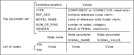
A connector or component symbol in Diagram must have a certain set of parameters. Two parameters types can be included:
• Symbol definition parameters to identify the symbol.
• Node parameters identifying nodes. (If nodes are necessary in the symbol.)
Symbols may be assigned to any component or connector parameters.
You can modify symbolic representations of components and fixed connectors (such as the shape of the symbol, nodes, and the location of notes) only by redefining the reference symbol definition. If the symbols are defined as Variable Drawing Units in the symbol definition, then you do not need to redefine the symbol to change its size.
If you redefine a symbol, all component/connector instances in the diagram that reference the same symbol also change.
|
|
You cannot redefine a Parametric connector.
|
Symbol Instances
When you add a symbol instance, you specify:
• The symbol definition to be used
• Where to place it in the diagram
• How large to make the symbol
• Its parameters (diagram objects only)
To add symbol instances you can:
• Place them as you would in a drawing.
• Place them as a diagram object such as a single-view component, a single-view connector, or a parametric connector. In the case of the parametric connector, the definition is actually a part of the instance.
• Place them as part of a multiple view component or a multiple view connector.
If an application uses a symbol with required parameters, but they are missing, the system issues an error message and you can edit the symbol parameter file. The next figure shows the format of the parameter file.
Parameter Set Format

Symbols containing an individual parameter set are used to create electrical diagrams. You can define Diagram symbols in Drawing mode and Diagram mode. However, if you want to use them in Diagram, you must define them as components or connectors by providing the parameter set appropriate for the type of object the symbol represents (component or connector). The following tables list component and connector parameters (the required parameters are shown in bold type).