Solid-Shell Links
When you select the Create Solid-Shell Links check box on the FEM Mesh Settings dialog box , links are created automatically for all the solid-shell interfaces that have a bonded connection and merged nodes. Creation of links connects the shell and solid rotation at the interface and allows moments to be correctly transferred between the solid and shell elements.
The following figure illustrates the creation of links at a solid-shell interface.
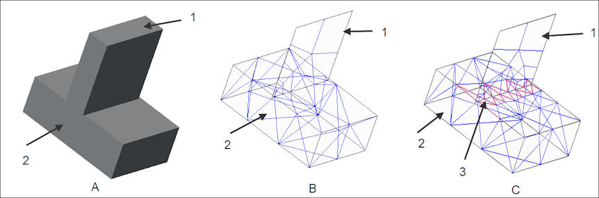
1. Shell
2. Solid
3. Links created at solid-shell interface
The model in figure A has a solid-shell interface. In figure B, the model is meshed after clearing the Create Solid-Shell Links check box. In figure C, the model is meshed with the Create Solid-Shell Links check box selected.
A line of elements is created on both sides of the interface edge to approximate the original solid geometry in that area. The size of the elements along the interface is of the order of half the shell thickness. Shell and solid elements are connected by weighted links. The links connect the solid along the interface surface of the original shell geometry. The weighted links are displayed in pink in figure C. The dependent side of a weighted link is the shell edge node while the independent sides are the closest solid nodes on the adjacent solid surfaces. Each link has 3 or 4 independent nodes on the solid surface.
To avoid creation of such links on a specific interface, you must prevent the nodes there from being merged. To do this, create a free interface between the shell and the solid, if possible. Alternately, clear the Merge Coincident Nodes check box on the Interface Definition dialog box when creating a bonded interface. In order to prevent these links from being created throughout the model, clear the Create Solid-Shell Links check box that is selected by default. The default setting is controlled by the fem_mesh_link_solid_shell configuration option.
Return to FEM Mesh Settings Dialog Box.