Example: Creating Load Paths for Pre-meshed Components
The easiest way to learn about creating load-transmitting connections for pre-meshed components within a hierarchical mesh is by reviewing the steps involved. The following sample outlines this process.
While you do not need to follow the exact order of these steps when you work with your own assemblies, be sure you understand the impact of each one and can reproduce its effect within your own process. For example you can create top-level assembly connections before or after you create hard points on pre-meshed components. You just need to make sure that the hard points are in place before you mesh the individual component.
This sample process begins in part mode if the pre-meshed component is a part or is in assembly mode if the pre-meshed component is a subassembly.
1. Open the part or subassembly. At this point the part or subassembly should not yet have a mesh. If it does, erase the mesh.
2. Create datum points wherever you want to form connections with the top-level assembly. As Creo Simulate uses these datum points to determine the load path, consider the distribution and placement carefully.
3. Define each datum point as a hard point mesh control, and then mesh the model. The resulting mesh establishes a node at every hard point.
4. In assembly mode, open the top-level assembly. The component meshed in step 3 should appear with its mesh.
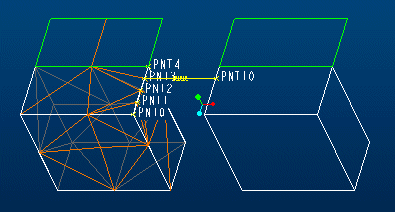
5. Connect all pre-meshed components in the load path to the top-level assembly by creating a beam, spring, contact, rigid link, or weighted link. For the pre-meshed components, be sure to use one of the hard points established in step 3. For the top-level components, use any applicable geometry as the end of the idealization or link, as shown in this example:

Here, there is a spring idealization that connects hard point 3 on the meshed part to datum point 10 on the unmeshed part.
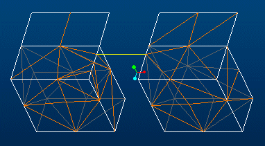
6. Mesh the top-level assembly. When the mesh generator encounters connections with pre-existing meshes, it uses the hard points as element nodes and routes the beam, spring, contact, or rigid or weighted link to the meshed nodes, as shown below:

Note that the mesh of the left part has nodes at all the hard points along the edge, but the elements of the left and right parts only have a coincident node where the spring is. These two nodes are where the load transmits.
The mesh on the left is an inherited mesh—a pre-existing mesh that the top-level assembly mesh inherits—while the mesh on the right and the spring element are both part of the top-level assembly mesh.
This process varies slightly if you are connecting two pre-meshed components together. In this case, you need to create the connection hard points for both components before generating the respective component meshes. After both components have meshes that account for the hard points, you mesh the connections in the top-level assembly. In this case, the assembly mesh consists of only those elements that represent connection idealizations.
Once you understand the steps just described and their implications, you may want to review some techniques that will help you create desired effects and handle special situations.
Return to Load Paths for Hierarchical Meshes.