To Specify Parameters for Measure Step
1. Do one of the following operations:
◦ Select the measure step in the Model Tree, right-click, and choose Edit Step Parameters.
◦ Select the measure step in the Model Tree and click > > .
◦ Select Parameters in the MEASUREMENT STEP dialog box.
The Edit Parameters dialog box opens. This dialog box contains the parameters table, which lists all the parameters that are visible at the measure sequence level.
2. To display parameters that belong to a particular category only, choose the appropriate category from the Category drop-down menu.
3. Click > to open the Column Setup Builder dialog box, which has options to add or remove columns, rearrange columns, and set the default width of the columns in the parameters table.
4. Each column of the parameter table displays a property of the parameter as explained below. These properties can be modified in the Parameters Setup dialog box only.
◦ Comments—Comment for the parameter
◦ Parameter ID—Name used to represent the parameter in relations
◦ DMIS—Depending on whether the option is on or off, specifies whether the parameter should be included in the DMIS Data output. The output format is as follows:
TEXT / ‘<parameter_name>:<parameter_value>'
5. Type the value of the parameter in the Value column of the parameters table. For required parameters, this cell is highlighted in light yellow color. If you enter an invalid value, a warning message is displayed and the previous value of the parameter is restored.
For parameters that accept string values, this field turns into a drop-down menu with the allowable values. Select the appropriate value.
6. Click  to open the Relations dialog box and modify relations.
 to open the Relations dialog box and modify relations.
7. To sort parameters by their names or values, click the corresponding column header. Click the column header again to sort in descending order. Alternatively, click an option from the > menu.
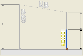
8. Click Show Details to view the graphical illustration of the selected parameter. The illustration is displayed for basic parameters only. If the parameter has a predefined set of values, the graphical illustration corresponding to the specified value is displayed. For example, the following graphic is displayed when you select the MEAS_APPR_DIST parameter:

• The graphical illustration represents the operation for which the parameter is used. • The location of the parameter in the graphic is highlighted. |
9. Click Hide Details to hide the graphical illustration.
10. Using the following options on the File menu, you can save parameters and their values to the disk or retrieve the stored parameters from the disk:
◦ Save As—Saves the parameters and their values to disk. Enter a file name in the Save a Copy dialog box that appears. The file is saved with the extension .mea.
◦ Open—Retrieves saved parameters and values from another measure sequence. In the File Open dialog box that appears, specify the file containing saved parameters.
◦ Open Site—Retrieves saved parameters from a site file. You must, click to open the File Open dialog box and specify the site file.
11. Using the following options on the Edit menu, you can :
◦ Copy—Copies currently selected cell or cells in the parameters table. You can then paste the copied values to a different cell or cells.
◦ Copy Parameter ID—Copies the parameter ID corresponding to the selected row.
◦ Paste—Pastes copied values to the selected cell or cells.
◦ Copy From Probe—Contains options to copy probe parameters to the measure sequence. Click the relevant option.
◦ Inherit From Site— Contains options to inherit parameters from sites defined in the manufacturing model. The site selected from which to inherit parameters is marked on the Inherit From Site menu. Choose None to not inherit parameters from a site.
◦ Copy from Step—Copies parameters from a previously defined step in the current CMM Model.
12. Click > to open the Search dialog box which contains options to search for a parameter.
13. Click > to open the INFORMATION WINDOW dialog box, that displays all information about the current measure step.
14. Click > to open the Relations dialog box and modify relations.
15. Click > to open the Column Setup Builder dialog box that has options to add or remove columns in the parameters table.
16. Click OK to save all changes and close the dialog box. This option is available only after you provided the values for all the required parameters.
17. Click Cancel to discard all changes and close the dialog box. Alternatively click > .