To Define Fillet Weld Preferences—ANSI
The preferences you define remain active for the current session.
1. Click >  Welding. The Welding tab opens.
Welding. The Welding tab opens.2. Click  Preferences. The Weld Preferences dialog box opens.
Preferences. The Weld Preferences dialog box opens.3. In the Weld preference for standard box, select ANSI.
4. Select Fillet on the list on left side of the dialog box.
5. To define the default weld dimensioning scheme, click the Shape tab, and select an option:
◦ D x D, and then type a length value to define two legs of equal length.
◦ D1 x D2, and then type a length value in the D1 box, and a different value in the D2 box, to define legs of different length.
◦  , and then type an angle value to define the angle of the projection of the side 1 chain to the side 2 surface.
, and then type an angle value to define the angle of the projection of the side 1 chain to the side 2 surface.◦  , and then select edges.
, and then select edges.6. Click the Intermittent tab, select the Intermittent check box, and set these preferences:
◦ To set the method of determining the spacing between the intermittent weld segments, select a Pitch option:
▪ Automatic
▪ Type or select a value to set the intermittent weld segment length.
▪ To set the number of intermittent weld segments that are created, type or select a value for the Number of welds.
▪ To set the method for distributing the intermittent weld segments along the trajectory, next to Weld spacing, select an option:
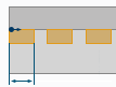
▪ End with gap—Distribute the weld segments so every weld is followed by a gap. There is a weld at the start of the trajectory, and a space at the end. The gap length is automatically adjusted to fit.
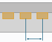
▪ End with weld—Distribute the weld segments symmetrically from the middle of the trajectory, with a weld at the start of the trajectory, and a weld at the end. The gap length is automatically adjusted to fit.
▪ By Value
▪ Type or select a value for distance between intermittent weld segments. For ANSI, the pitch is measured from the middle of one weld segment to the middle of the next weld segment.
▪ Type or select a value for the intermittent weld segment length.
7. Click the Options tab, and set these preferences:
◦ To set the area of the weld cross section, type or select a value in the Weld cross section box.
◦ Under Weld material, select a predefined weld material, or click Define and create a new material in the Weld Materials dialog box.
◦ Under Weld process, select a predefined weld process, or click Define and create a new process in the Weld Processes dialog box.
◦ To define the visibility of the all-around weld symbol, select an option from the  All-around weld list:
All-around weld list:▪ No—Do not show the all-around weld symbol in the weld feature symbol, even when the feature detects a closed weld trajectory.
▪ Yes—Show the all-around weld symbol in the weld feature symbol, even when the feature detects an open weld trajectory.
▪ Automatic—Show the all-around weld symbol in the weld feature symbol only when the feature detects that all the weld trajectories are closed.
◦ To define the weld as a field weld, select the  Field weld check box.
Field weld check box.◦ To define the weld finish, select an option from the Finish list.
◦ To define the weld contour, select an option from the Contour list.
8. Click the Appearance tab, and set these preferences:
◦ Select a previously defined appearance from the Appearance list.
◦ To set the appearance of lightweight weld trajectories, type or select a value for the curve thickness in the Curve thickness box.
9. Click the Properties tab, and set additional preferences as needed.
10. Click OK.