About the Fillet Weld User Interface
The Fillet Weld tab consists of commands, tabs, and shortcut menus. Click >  Welding. On the Welding tab, click
  Fillet Weld.
Welding. On the Welding tab, click Fillet Weld.Commands
The commands are context-sensitive.
• Position
◦  Single-sided—Creates a single-sided weld.
Single-sided—Creates a single-sided weld.◦  Double-sided—Creates a symmetrical double-sided weld.
Double-sided—Creates a symmetrical double-sided weld.• Dimensioning Scheme
◦ Dimensioning scheme list—Sets the type of dimensioning and reference scheme for the current active weld set.
▪ D x D (ANSI only)—One length dimension for two equal legs
▪ D1 x D2 (ANSI only)—Two different length dimensions, one for each leg
▪ A (ISO only)—Distance from the weld surface to the trajectory (throat thickness)
▪ Z (ISO only)—Maximum leg length
▪ Z1 x Z2 (ISO only)—Two different length dimensions, one for each leg
▪  —Angle of the projection of the side 1 chain to the side 2 surface
—Angle of the projection of the side 1 chain to the side 2 surface▪  —No dimensioning scheme
—No dimensioning scheme◦ Dimensioning boxes—Sets values for the selected weld dimensions.
• Lightweight Weld Trajectory
◦  Automatic—Automatically calculates lightweight weld trajectories. Not available when the dimensioning scheme is selected.
Automatic—Automatically calculates lightweight weld trajectories. Not available when the dimensioning scheme is selected.◦  Manual—Manually calculates lightweight weld trajectories (user-defined).
Manual—Manually calculates lightweight weld trajectories (user-defined).Tabs
• Location
◦ Weld sets list—Lists references sets. One set of references is used to define each side of the weld. For example, for both sided (symmetrical) welds, there are two reference sets, Arrow Side and Other Side.
◦ Side 1—Defines references for side 1 of the weld. The collectors vary based on the selected dimensioning scheme.
▪ Chains collector—Collects chains. Available when the dimensioning scheme is or .
or .▪ Side 1 Weld Surfaces collector—Available when the dimensioning scheme is D x D, D1 x D2, A, Z, Z1 x Z2, or if needed to display additional references for solid welds, .
.◦ Side 2—Defines references for side 2 of the weld. The collectors vary based on the selected dimensioning scheme.
▪ Chains collector—Available when the dimensioning scheme is .
.▪ Side 2 Weld Surfaces collector—Available when the dimensioning scheme is D x D, D1 x D2, A, Z, Z1 x Z2, or if needed to display additional references for solid welds, , or .
, or .◦ Details—Opens the Surface Sets or Chain dialog box depending on the selected reference type.
◦ Allow tangent propagation check box—Extends a weld trajectory in both directions along adjacent tangent surfaces during weld calculation.
◦ Treat side surfaces as contact surfaces check box—Creates a weld trajectory along the edges formed by the boundary of the area where two contact surfaces overlap. Available when the D x D, D1 x D2, A, Z, or Z1 x Z2 dimension scheme is selected.
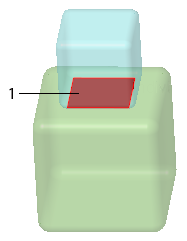
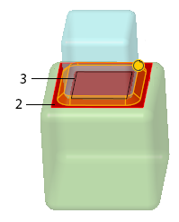
1. Selected surface at the bottom of the blue block
2. Selected surface at the top of the green block
3. Weld trajectory is created along the edges formed by the boundary of the area where the two contact surfaces overlap
◦ Weld joints table—For welds with surface references only, lists joints (trajectory pieces) for inclusion in or exclusion from the trajectory when you create weld geometry. For each joint, you can define a joint starting point, modify joint ends, and attach a weld symbol to the specific joint.
▪ Details—Opens the Joint dialog box where you view and edit joint properties. Available when a joint is selected in the Weld joints table.
◦ Restore Default button—Restores the default calculated trajectory.
◦ Lightweight weld trajectory collector—Collects chain references for user-defined (manual) lightweight weld trajectories when Manual is selected.
Manual is selected.▪ Details—Opens the Chain dialog box.
◦ Flip material side button—Flips the material side 180 degrees. Available when the or dimension scheme is selected.
or dimension scheme is selected.• Intermittency
◦ Intermittent weld check box—Defines the weld as intermittent.
▪ Type
▪ Linear—Uses linear pitch (distance between weld segments) to set dimensions for intermittent welds.
▪ Angular—Uses angular pitch (angle between weld segments) to set dimensions for intermittent welds.
▪ Pitch—Sets the method to calculate the spacing between the intermittent weld segments.
▪ Automatic—Calculates the pitch automatically. When selected, the Weld spacing options become available.
▪ By value—Defines the pitch by using a value. When selected, the Number of welds check box becomes available.
▪ Staggered check box—Staggers the welds in double-sided symmetrical intermittent welds.
▪ Weld segment value box—Defines the weld segment length.
▪ Defines a linear value for the weld segment length when the type is set to Linear.
▪ Defines a value in degrees for the weld segment length when the type is set to Angular.
▪ Pitch value box—Defines the pitch value. Available when the pitch is set to By value.
▪ ANSI—Pitch is measured from the middle of one weld segment to the middle of the next weld segment.
▪ ISO—Pitch is measured from the end of one weld segment to the beginning of the next weld segment.
▪ Number of welds check box—Makes the Number of welds value box available when the pitch is set to By value. If this check box is not selected, then welds are created along the entire length of the trajectory.
▪ Number of welds value box—Sets a value for the number of intermittent weld segments that are created.
▪ Weld spacing—Sets the method of distributing the intermittent weld segments along the trajectory when the pitch is set to Automatic.
▪ End with gap—Distributes the weld segments so every weld is followed by a gap. There is a weld at the start of the trajectory, and a space at the end. The gap length is automatically adjusted to fit.
▪ End with weld—Distributes the weld segments symmetrically from the middle of the trajectory, with a weld at the start of the trajectory, and a weld at the end. The gap length is automatically adjusted to fit.
• Options
◦ Weld geometry type—Sets surface, light, or solid geometry to represent the weld.
◦ Weld cross section—Selects the method used to define the weld cross section area when surface or light geometry represents the weld:
▪ By Reference—Defines the weld cross section area using a plane that you select.
▪ By Value—Defines the weld cross section area using a value that you enter.
◦ Weld material—Selects a predefined welding material.
▪ Define—Opens the Weld Materials dialog box.
◦ Weld process—Selects a predefined welding process.
▪ Define—Opens the Weld Processes dialog box.
◦  All-around weld—Defines the visibility of the all-around weld symbol:
All-around weld—Defines the visibility of the all-around weld symbol:▪ No—Does not show the all-around weld symbol in the weld feature symbol, even when the feature detects a closed weld trajectory.
▪ Yes—Shows the all-around weld symbol in the weld feature symbol, even when the feature detects an open weld trajectory.
▪ Automatic—Shows the all-around weld symbol in the weld feature symbol only when the feature detects that all the weld trajectories are closed.
◦  Field weld check box—Defines a weld as a field weld that will be done in another location.
Field weld check box—Defines a weld as a field weld that will be done in another location.◦ Finish list (ANSI)—Defines a weld finish.
◦  Finish check box (ISO only)—Sets the weld finish option to ISO standards.
Finish check box (ISO only)—Sets the weld finish option to ISO standards.◦ Contour list—Defines the weld contour after weld finishing.
◦ Display sequence ID check box—Shows or hides the sequence ID number in the welding symbol tail.
◦ Keep ID in sequence check box—Keeps the weld ID number the same regardless of subsequent actions (such as deleting previously defined weld features or reordering welds to different locations in the regeneration order).
• Symbol
◦ Display identification line check box—Displays the identification line in the weld symbol. Available for ISO welds.
▪ Below reference line—Places the identification line in the weld symbol below the reference line.
▪ Above reference line—Places the identification line in the weld symbol above the reference line.
◦ Create as Other Side symbol check box—Create the symbol to represent the weld on the other side of the joint.
▪ Next leader—Sets the placement method for the next leader.
▪ Attachment collector—Collects a planar reference on which to place the symbol.
◦ Preview—Displays an image of the welding symbol.
◦ Add Note—Contains the text you type for a user-defined note.
• Properties
◦ Name box—Sets the weld name.
◦  —Opens the Feature info window for a weld feature.
—Opens the Feature info window for a weld feature.◦ Feature Parameters Define button—Opens the Parameters dialog box for a weld feature.
Shortcut Menus
Shortcut menu commands are context sensitive depending on the location of your cursor.
While the Fillet Weld tab is open, right-click the graphics window any place except over a handle to display the following shortcut menu commands:
• Side 1—Activates the Side 1 collector.
• Side 2—Activates the Side 2 collector.
• Lightweight weld trajectory—Activates the Lightweight weld trajectory collector.
• Weld Cross Section—Activates weld cross section collection.
• Clear—Empties the current active collector.
• Flip material side—Flips the material side 180 degrees.
• Allow tangent propagation—Extends a weld trajectory in both directions along adjacent tangent surfaces during weld calculation.
• Treat side surfaces as contact surfaces—Creates a weld trajectory along the edges formed by the boundary of the area where two contact surfaces overlap. Available when the D x D, D1 x D2, A, Z, or Z1 x Z2 dimension scheme is selected.
• Intermittent—Activates intermittency functionality.
• New Set—Activates location reference collection in the graphics window.
Place your cursor in a collector that contains a reference and right-click to display the following shortcut menu commands:
• Remove—Deletes a selected reference in a collector.
• Remove All—Deletes all selected references contained in a multiple reference collector.
• Information—Displays information about the selected reference.
Select a welding feature in the Model Tree and right-click to display the following welding-specific shortcut menu commands:
•  Change Weld Material—Opens the Weld Material Selection dialog box.
Change Weld Material—Opens the Weld Material Selection dialog box.•  Change Process—Opens the Process Selection dialog box.
Change Process—Opens the Process Selection dialog box.