Exercise 2 — Defining Electric Nets
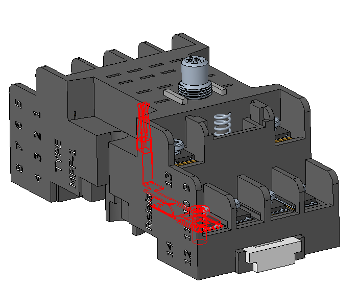
1. In the tab, under Potential-Free, select the net that highlights the components as shown in the following image.
2. Right-click and select Rename.
3. In the Rename box, type DC+ and click  .
.
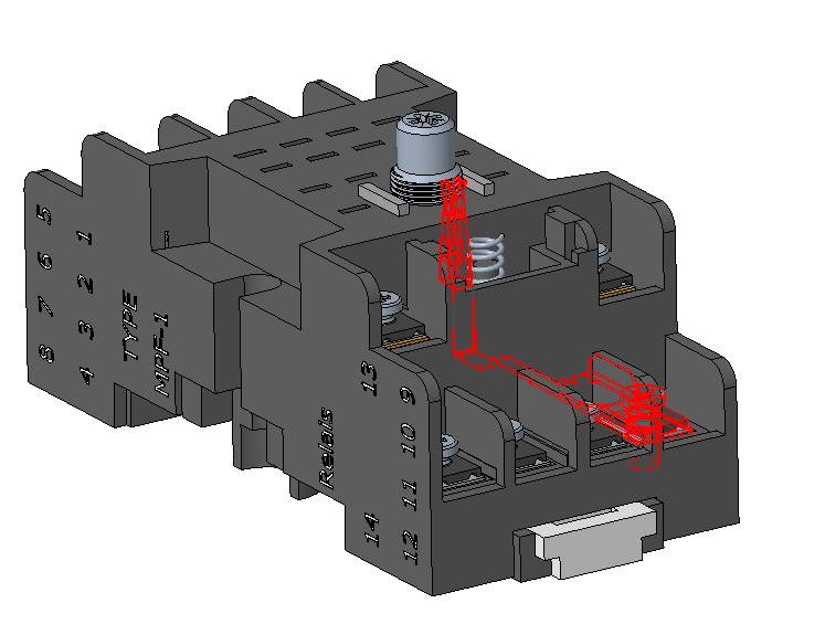
.4. Under Potential-Free, select the net that highlights the components as shown in the following image.
5. Right-click and select Rename.
6. In the Rename box, type DC- and click .
.7. In the Auto merge distance box, adjust the value to 0.10 mm.
8. Click Auto Merge Nets to automatically combine all the nets with a distance less than 0.10 mm from each other.
The text color of merged net changes to blue.
9. Right-click the merged net and select Show Content. In the Net Content dialog box, you can see a list of all components of the net.
10. Click Close.
11. Select nets DC+ and DC-, right-click, and select Set Potential. The nets appear under Potential.
12. From the In Graphics toolbar, click  and select saved view 2. The orientation of the assembly changes.
and select saved view 2. The orientation of the assembly changes.13. Change the selection filter located in the lower right of the graphics window to Surface.
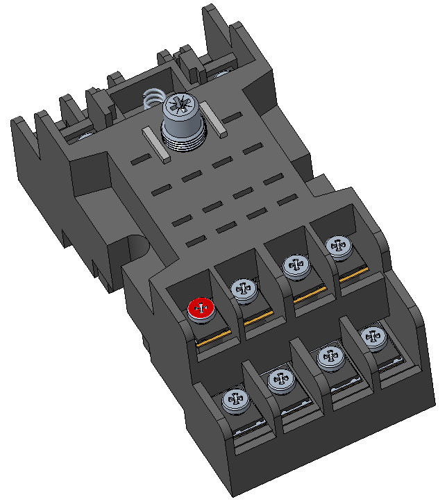
14. Select the four surfaces as shown in the figure.

15. Right-click one of the selected surfaces and click Set Potential.
16. From the In Graphics toolbar, click and select saved view 3. The orientation of the assembly changes.
and select saved view 3. The orientation of the assembly changes.17. Select the surface as shown in the figure. Right-click the surface and select Set Grounded.
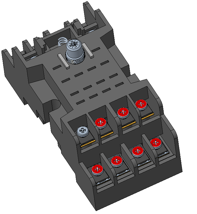
18. Select seven surfaces as shown in the figure.
19. Right-click one of the selected surfaces and select Set Potential.
20. Click Apply Electric Nets. The Electric Nets tab closes and the Analysis tab opens.