Multiphase Flow for a Fuel Tank: Exercise 2—Creating Boundary Conditions
1. Under Domains, right-click NOZZLE:Body 1 and select  Add Boundary Condition. The Surface Sets dialog box opens.
Add Boundary Condition. The Surface Sets dialog box opens.2. Select Nozzle_Air_Outlet as shown in the figure below.
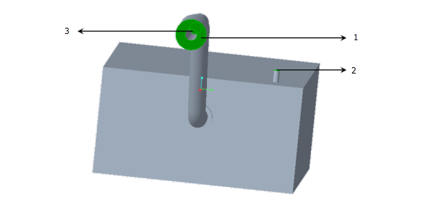
1. Nozzle Air Outlet
2. Tank Air Outlet
3. Nozzle Fuel Inlet
3. Click OK. Under General Boundaries a new entity BC_00001 is created.
4. Under Domains, right-click NOZZLE:Body 1 and select Add Boundary Condition. The Surface Sets dialog box opens.
Add Boundary Condition. The Surface Sets dialog box opens.5. Select Nozzle_Fuel_Inlet as shown in the figure.
6. Click OK. Under General Boundaries a new entity BC_00002 is created.
7. Under Domains, right-click TANK:Body 1 and select Add Boundary Condition. The Surface Sets dialog box opens.
Add Boundary Condition. The Surface Sets dialog box opens.8. Select Tank_Air_Outlet as shown in the figure.
9. Click OK. Under General Boundaries a new entity BC_00003 is created.
10. Right-click and rename the following boundary conditions:
◦ BC_00001 as Nozzle_Fuel_Inlet
◦ BC_00002 as Nozzle_Air_Outlet
◦ BC_00003 as Tank_Air_Outlet