External Air Flow for a Truck: Exercise 4—Assigning Boundary Conditions
For boundary conditions, the fluid behavior and properties are specified at all bounding surfaces of the fluid domain.
Specifying Inlet Boundary Conditions
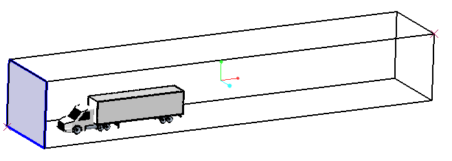
1. Under  Boundary Conditions >
  General Boundaries, select outside_dir1_min.
Boundary Conditions > General Boundaries, select outside_dir1_min.2. In the Model tab, for Flow, select the following values for the options listed:
◦ Flow — Specified Velocity
◦ Under Method, set Velocity to 20,0,0
Specifying Outlet Boundary Conditions
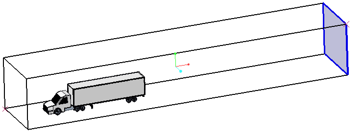
1. Under Boundary Conditions > General Boundaries, select outside_dir1_max.
Boundary Conditions > General Boundaries, select outside_dir1_max.2. In the Model tab, for Flow, select the following values for the options listed:
◦ Flow — Specified Pressure Outlet
◦ Pressure — 0 Pa
Specifying Other Boundary Conditions

1. In the Flow Analysis Tree, under Boundary Conditions > General Boundaries, select outside_dir2_max, outside_dir3_max, and outside_dir3_min.
Boundary Conditions > General Boundaries, select outside_dir2_max, outside_dir3_max, and outside_dir3_min.2. In the Model tab, for Flow, select the following values for the options listed:
◦ Flow — Specified Pressure Outlet
◦ Under Velocity Profile, set Back Flow Velocity(optional) to 20,0,0
Specifying Expressions to calculate Drag Coefficient
1. In the Flow Analysis Tree, select  Physics.
Physics.2. In the Operations group, click  Expression Editor.
Expression Editor.3. In the Expression Editor box, enter the following:
V_fs = 20 # flow velocity
rho = 1.176 # density
A = 9.51474 # frontal area
#Drag force
D = flow.px@CAB + flow.tx@CAB + flow.px@TIRE_1 + flow.tx@TIRE_1 + flow.px@TIRE_2 + flow.tx@TIRE_2 + flow.px@TIRE_3 + flow.tx@TIRE_3 + flow.px@TIRE_4 + flow.tx@TIRE_4 + flow.px@TIRE_5 + flow.tx@TIRE_5 + flow.px@TIRE_6 + flow.tx@TIRE_6 + flow.px@TIRE_7 + flow.tx@TIRE_7 + flow.px@TIRE_8 + flow.tx@TIRE_8 + flow.px@TIRE_L_1 + flow.px@TIRE_L_2 + flow.tx@TIRE_L_1 + flow.tx@TIRE_L_2 + flow.px@TRAILER + flow.tx@TRAILER
plot.Drag_Force_on_Truck = D
#plot.Drag_Force_on_Truck: Drag force
#Drag coefficient
C_d = D/(0.5*rho*V_fs*V_fs*A)
plot.Coefficient_of_Drag = C_d
#plot.Coefficient_of_Drag = Coefficient of Drag
4. Click OK.