Assembling Profiles on a Straight Curve
1. Click >  New Profile.
New Profile.◦ If the New Profile dialog box opens, click Section Type and then go to step 2.
◦ If the Select From Library dialog box opens, go to step 6.
2. From the Select From Library dialog box, you can select a profile section type from the library. Under Profiles, select the folder STEEL BEAMS MM and then select I BEAM. The Element Definition dialog box, from which you can select the standard and size of the I-beam, opens.
3. Under Type, select DIN 1025 IPB/HEB. The Size list opens.
4. Under Size select 120.
5. Click OK. The New Profile dialog box opens.
6. Click Next or middle–click to proceed with profile placement. The Position Profile dialog box opens.
7. Under Reference Method click  to activate assembling the profile on a straight edge or curve.
to activate assembling the profile on a straight edge or curve.8. Under References, click the box under Curve or edge to activate this collector.
9. Select the vertical curve as shown below. The assembled I-beam appears in a preview so that you can configure the position prior to committing to the final placement.

10. Under Rotate, click  to rotate the profile by 90 degrees. Notice that the preview updates.
to rotate the profile by 90 degrees. Notice that the preview updates.11. Click OK to complete profile placement. The Position Profile dialog box closes, the assembly of the I-beam is completed, and the New Profile dialog box opens.
12. Click  to select another section type.
to select another section type.13. In the Select from Library dialog select the section type RECTANGULAR TUBE.
14. In the Element Definition dialog box, select the standard DIN 2395 and size 120x80x4.00 and click OK.
15. In the New Profile dialog box click Next or middle-click to proceed with profile placement.
16. In the Position Profile dialog box click to activate assembling the profile on a straight edge or curve.
to activate assembling the profile on a straight edge or curve.17. On the model, referring to callout 1 in the picture below, select the first of the four highlighted curves.
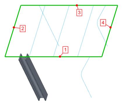
18. Under Rotate click to rotate the profile by 90 degrees.
to rotate the profile by 90 degrees.19. Click Repeat or middle–click to complete placement of the rectangular tube and continue with the next profile.
20. Referring to callouts 1, 2, and 3, repeat steps 17–19 for the remaining 3 highlighted curves.