Example: Remove Internal Geometry
When you create a fluid domain for a model, using any method other than the Enclosure Volume feature, you can run a study in which geometry that lies inside the fluid domain can be cut out of the fluid domain, when the study runs. This is a solver level Boolean subtraction operation.
The following example shows a jointed pipe with two inlets and one outlet. The fluid domain is the inner volume of the pipe and encloses a valve mechanism. You can study the flow behavior with and without the valve, and with different orientations of the valve, without creating a new fluid domain every time.
 1. Fluid domain (the green outline indicates the extent of the domain) 2. Inlet 1 3. Inlet 2 4. Outlet 5. Valve enclosed by fluid domain |
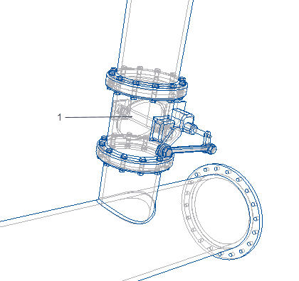 1. valve mechanism enclosed within fluid domain |
To view the flow results with the valve geometry present or removed, select the fluid domain in the Simulation Tree. Right-click and select or clear the Remove Internal Geometry check box. By default, the check box is cleared and the valve geometry is not subtracted from the fluid domain.
|
Results with Remove Internal Geometry check box cleared
|
Results with Remove Internal Geometry check box selected
|
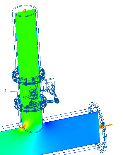 1. In this case the valve volume is not cut out from the fluid domain. |
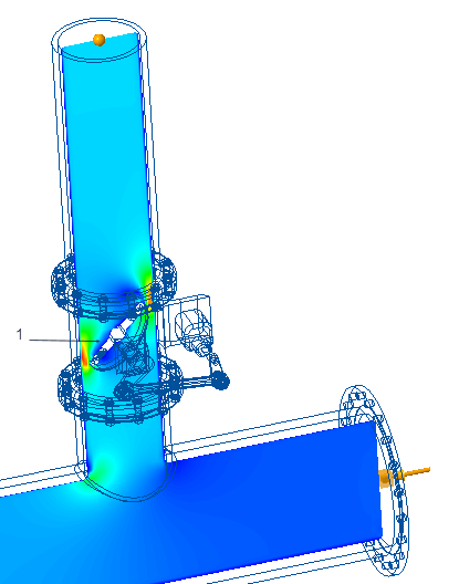 1. In this case the valve volume is cut out (Boolean subtraction) from the fluid domain. |