Guidelines for Bearing Loads
When working with bearing loads, keep the following guidelines in mind:
• Bearing loads are not available in FEM mode.
• You can apply this type of load to a non-right cylindrical surface with spline.
|
|
A bearing load applied to an elliptical surface in Wildfire 3.0 or earlier is invalid in Pro/Engineer Mechanica Wildfire 4.0 and later versions.
|
• The cylindrical surface must have a straight centerline.
• Although selection of conical surfaces for bearing loads is not recommended, you can select conical surfaces if you set the value of the configuration option sim_bearing_allow_cone_sel to yes.The selected surface must also meet the following criteria:
The difference between the larger and smaller radii of the cylindrical surface must be less than or equal to 10% of the larger radius.
1–(smaller radius)/(larger radius) <= 0.1 (larger radius)
In the following example the conical surface has the following properties:
◦ smaller radius = 22.8128
◦ larger radius = 25.0
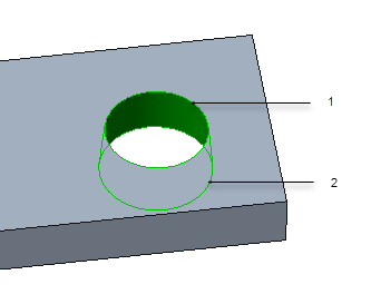
1. smaller radius = 22.8128
2. larger radius = 25.0
1–(smaller radius)/(larger radius) = 0.0875
0.1 (larger radius) =2.5
Hence these conical surfaces meet the criterion and you can select them when creating a bearing load.
• If you select several holes, while applying a bearing load, the load is not divided between the selected holes. Instead, each hole is assigned with the bearing load that you specified on the Bearing Load dialog box.
• You can apply this type of load to open surfaces. However, surfaces must be connected to form a portion of a cylinder. The software displays the bearing load distribution toward the inside of the surface region.
• The vector you specify must have at least one component that is not parallel to the axis of any hole you select. If you specify a vector that is fully parallel to the axis, the software does not accept the load.
• The software defines a bearing load distribution as a cosine distribution that does not vary down the length of the centerline. This distribution enables you to quickly apply compression-only bearing loads to cylinders and rings.
• If the load is not symmetrical about the axis and if the resultant load is not passing through the selected references, the load may create a moment about bearing axis. Use the > > command to check the resultant load.
Return to Bearing Loads.