Turbulent Flow
Pressure Drop Along Pipe Length – Turbulent
Problem Statement: 3D turbulent flow in a straight pipe is modeled using the standard k-ε turbulence model.
References: F.M. White. Fluid Mechanics. 3rd Edition. McGraw Hill Book Co. Inc., New York, NY, 1994.
Fluid Properties | Geometric Properties | Working Conditions |
|---|---|---|
Density = 1.225 kg/m3 Viscosity = 1.7894e-5 Pa-s | Radius = 0.002 m Length = 2 m | Inlet Velocity = 50m/s Outlet Pressure = 0 Pa |
Result Comparison
Results | Analytical | Creo Flow Analysis | % Difference |
|---|---|---|---|
Pressure Drop (Pa) | 0.743 | 0.73 | 0.48 |
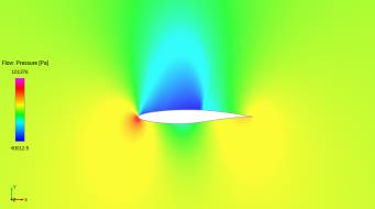
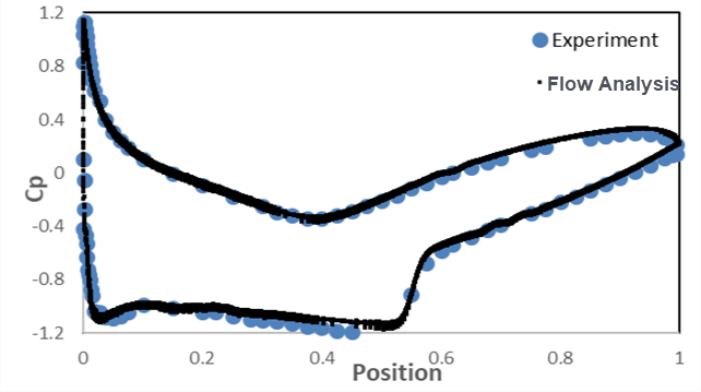
Transonic Flow Over an Airfoil RAE2822
Problem Statement: 2D transonic flow is modeled around an airfoil RAE2822 under wind tunnel conditions using the standard k-ε turbulence model.

Chord Length = 1 m
References: P.H. Cook, M.A. McDonald, M.C.P. Firmin. “Aerofoil RAE 2822 - Pressure Distributions, and Boundary Layer and Wake Measurements.” AGARD Advisory Report No. 138.
Fluid Properties | Geometric Properties | Working Conditions |
|---|---|---|
Air Density = Ideal Gas Law Viscosity= 3.54822 X 10 -5 kg/ ms | RAE 2822 Airfoil AoA = 2.31 deg Wind tunnel height = 72 m Wind tunnel length = 96 m | M = 0.729 Pressure at boundaries = 71154 Pa Temperature at boundaries = 271 K |
Result – Pressure contours around airfoil
Result Comparison – Lift and drag coefficients
Results | Target | Creo Flow Analysis | Percent Error |
|---|---|---|---|
Lift Coefficient | 0.743 | 0.73 | 1.75 |
Drag Coefficient | 0.0127 | 0.0126 | 0.79 |
Result Comparison – Coefficient of pressure distribution
Turbulent Flow Over A Backwards Facing Step
Problem Statement: 2-D turbulent flow with separation and reattachment is modeled for a backwards facing step with the Renormalization Group k-ε model.
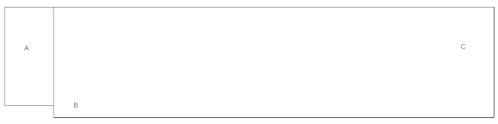
• A = Inlet
• B = Step
• C = Outlet
References: D.M. Driver, H.L. Seegmiller, "Features of a Reattaching Turbulent Shear Layer in Divergent Channel Flow". AIAA Journal,Vol 23, pp. 163-171, 1985.
Fluid Properties | Geometric Properties | Working Conditions |
|---|---|---|
Density: 1 kg/m3 Viscosity: 0.0001 kg/m-s | Step height = 1 m Length of the channel = 34 m Height of the channel = 9 m | Inlet: Fully developed velocity profile at 3.74 m/s Outlet: Atmospheric pressure |
Result Comparison – Reattachment length
The reattachment length is the distance from the step at which the flow resumes in the positive flow direction. The experiment provides a range for the reattachment length.
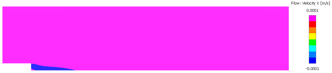
Reattachment Length | |
|---|---|
Experiment | Creo Flow Analysis |
x/H = 6.16 – 6.34 | x/H = 6.21 |
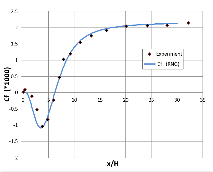
Result Comparison – Skin friction coefficient
Prediction of the reattachment point downstream of the step was determined in the experiment by the following:
• Laser oil-flow interferometer measurements of skin-friction
• Interpolation of the zero skin-friction location. The experimental and the CFD results along the wall are compared below.
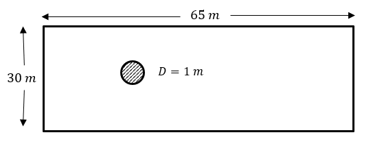
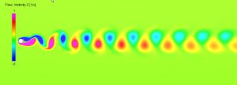
Vortex Shedding Over A Cylinder
Problem Statement: Flow over a cylinder is modeled using the standard k- ε turbulence model.
References: Williamson, C. H. K. (1988). Defining a universal and continuous Strouhal–Reynolds number relationship for the laminar vortex shedding of a circular cylinder. Physics of Fluids.
Fluid Properties | Geometric Properties | Working Conditions |
|---|---|---|
Density=1 kg/m3 Viscosity= 0.01 Pa-s | See Image Above | Transient = 0.01 s Inlet velocity = 1m/s Outlet pressure = 0 Pa |
Results – z-Vorticity after 150 s
Result Comparison – Strouhal number
The Strouhal number measures the shedding frequency.
Result | Target | Creo Flow Analysis | % Difference |
|---|---|---|---|
Strouhal Number | 0.164 | 0.165 | 0.61 |
Transitional Recirculatory Flow Inside a Ventilation Enclosure
Problem Statement: 3D recirculatory flow is modeled in a ventilation enclosure using the standard k-ε model.
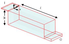
• I = Inlet
• O = Outlet
References: P.V. Nielsen, A Restivo, J.H. Whitelaw, “The Velocity Characteristics of Ventilated Rooms”, Journal of Fluids Engineering, Vol 100, pp.291-298 , 1978.
Fluid Properties | Geometric Properties | Working Conditions |
|---|---|---|
Density = 1.1766 kg/m3 Viscosity = 1.853e-5 Pa-s | L = 267.9 mm W = 89.3 mm Inlet height = 5 mm Outlet height = 14.3 mm | Inlet velocity = 15.78 m/s Outlet pressure = Atmospheric |
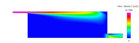
Results – X-Velocity contours at centerline
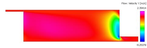
Results – Y-Velocity contours at centerline
Result Comparison – Normalized velocity along the y-direction of the enclosure
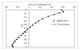
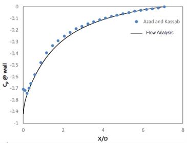
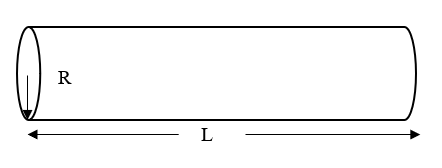
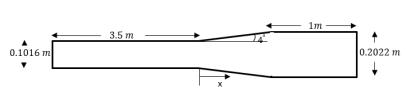
Turbulent Flow in a Diffuser
Problem Statement: 3D turbulent flow in a diffuser is modeled using the standard k- ε turbulence model.
References: Azad, R. S., & Kassab, S. Z. (1989). Turbulent flow in a conical diffuser: Overview and implications. Physics of Fluids A: Fluid Dynamics, 1(3), 564–573.
Fluid Properties | Geometric Properties | Working Conditions |
|---|---|---|
Density = 1.15758 kg/m3 Viscosity = 1.8406 x 10⁻⁵ Pa-s | See Image Above | Inlet velocity = 18.06 m/s Outlet pressure = 0 Pa |
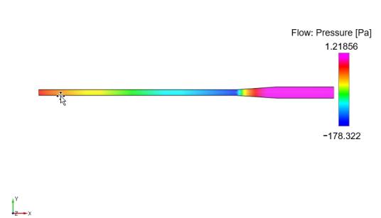
Results – Pressure contours
Results Comparison – Coefficient of pressure along diffuser wall