Example: Applying a Displacement Constraint from a Remote Point
Use the Apply from remote point option to apply a constraint from a point that is not on the model you are working on. Some use cases are as follows:
1. Use Case 1: To reduce the size of the model for which you are running the simulation.
Consider a very long beam that is fixed at one end and free at the other end. The beam carries a load at the free tip while the other end is fixed. Most of the stresses occur closer to the fixed end of the beam. In order to reduce the overall size of the model you can consider only a much smaller portion of the beam closer to the fixed end only, and apply a remote constraint from a point originating where the original free end of the beam is.
2. Use Case 2: To model a constraint from a point on a different component in an assembly without including that component in the simulation study.
In the following example the circular ring in the model is loaded by applying a force load to the top hole and constrained by applying a fixed constraint to the bottom hole and a displacement constraint to the surface. The remote point is not a part of the model.
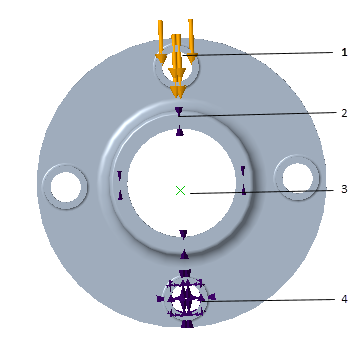
1. Force Load —1000 N along the negative X– direction
2. Displacement constraint applied to this surface from a remote point
3. Remote point from where the displacement constraint is applied
4. Fixed displacement
When you select different formulations of the constraint the results seen are different.
◦ Rigid—In this case the selected reference does not deform. This is similar to applying a rigid link between the point and the selected reference.
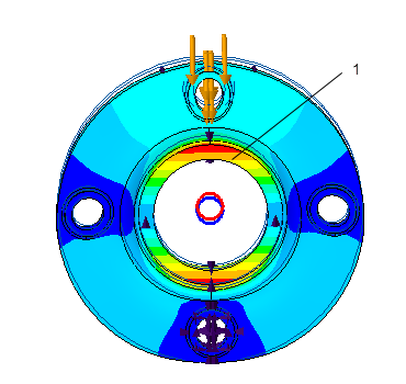
1. Ring retains circular shape
◦ Deformable—The selected reference is allowed to deform. This is similar to applying a weighted link between the point and the selected reference.
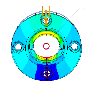
1. Ring deforms to an elliptical shape