About Design Rules
Design rules are guidelines for a design. They are based on the material type and the manufacturing process of a part. You can copy any number of design rule tables to a design, but only one rule table can be assigned to a part at a time. You can modify the rules for a design by changing the default values of one or more of the rules listed in the assigned rule table. The design rules and names are standard and cannot be changed, but they can be customized using relations.
A standard rule table includes the following elements:
|
Rule
|
Description
|
Default Value
|
Example
|
|---|---|---|---|
|
MIN_DIST_BTWN_CUTS
|
Checks the distance between two cuts or punches
|
5*T
|
 1. 2T or 3T or Greater 2. Stock Thickness (T) |
|
MIN_CUT_TO_BOUND
|
Checks the distance between a part edge and a cut or punch.
|
2*T
|
|
|
MIN_CUT_TO_BEND
|
Checks the distance between a bend-line and a cut or punch.
|
2.5 *T + R
|
 Where, H = Distance between the lowest edge and the hole T = Sheet metal thickness R = Bend radius Min H = 1.5*T+R |
|
MIN_WALL_HEIGHT
|
Checks the minimum bend height of formed walls.
|
1.5 * T + R
|
|
|
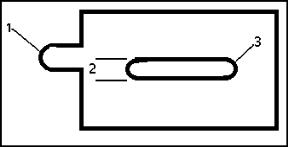
MIN_SLOT_TAB_WIDTH
|
Checks the minimum width of the slot.
|
T
|
 1. Slot Height 2. Slot Width (T) |
|
MIN_SLOT_TAB_LENGTH
|
Checks the minimum length of the slot.
|
0.7
|
|
|
MIN_LASER_DIM
|
For outer contour—checks if it has an arc with a diameter smaller than this value.
For inner contour—checks if it has an arc with a diameter smaller than this value and checks the distance between two parallel edges.
|
1.5*T
|
 1. Outer contour arc 2. distance between 2 parallel lines 3. Inner contour arc |