Nibble Edge Specific Parameters
Cut Options
• OUTPUT_TYPE—Affects the CL Data output. If the value is POINT_BY_POINT (the default), the cutter path is output as a sequence of GOTO statements. If the value is CYCLE_NIBBLE, the tool path for linear entities is output using the CYCLE/NIBBLE commands. For example, the cutter path for a single straight edge is output as follows:
◦ CYCLE / NIBBLE, n—(where n - number of hits, i.e., number of punches to be made from the previous hit position to the position specified by the subsequent GOTO statement)
◦ GOTO / x1, y1, z1—(to the beginning of the entity)
◦ GOTO / x2, y2, z2—(to the end of the entity)
◦ CYCLE / NIBBLE, OFF
Once a CYCLE/NIBBLE command is encountered, the same number of hits are used for each subsequent GOTO statement until another CYCLE/NIBBLE command or CYCLE/NIBBLE, OFF is reached.
Cut Params
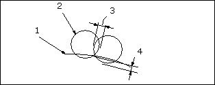
• NE_SCALLOP_HGT—Together with OVERLAP_DIST, SCALLOP_HGT can be used to control the next tool position with respect to the previous one (see SCALLOP_HGT and OVERLAP_DIST). The default SCALLOP_HGT is0, in which case the respective tool positions are defined by the OVERLAP_DIST parameter value. If a non-zero value is specified for SCALLOP_HGT, the system computes the overlap distance using this value, then compares it with the OVERLAP_DIST value you specified, and uses the lesser of the two.
• NE_OVERLAP_DIST—Define the overlapping of successive tool hits. OVERLAP_DIST is specified as an absolute value in the units of the workpiece. The default is 0.
SCALLOP_HGT and OVERLAP_DIST

1. Reference Edge
2. Tool
3. OVERLAP DIST
4. SCALLOP_HGT
• MAX_OVERLAP_DIST—Enable you to specify the maximum overlapping of successive tool hits. It is specified as an absolute value in the units of the workpiece. The default is a dash (-), which means to ignore.
• NE_SHAKEAWAY_DIST—Define the default distance to be left symmetrically on both sides of a shake away point or vertex. This value can be modified individually for each shake-away point or vertex. SHAKEAWAY_DIST is specified as an absolute value in the units of the workpiece.
• NE_OVERHANG_DIST—Define the default distance to go past the edge on each side of an overhang vertex. This value can be modified individually for each overhang vertex. OVERHANG_DIST is specified as an absolute value in the units of the workpiece.
Machine
• NE_LOCKED_TOOL_ORIENT—If the parameter is set to any value other than a dash (-) (the default), only linear entities that require tool orientation equal to this value are machined. The parameter value represents the angle to the X-axis of the Machine Csys. For example, to machine all edges parallel to the X axis of the Machine Csys, set LOCKED_TOOL_ORIENT to 0.
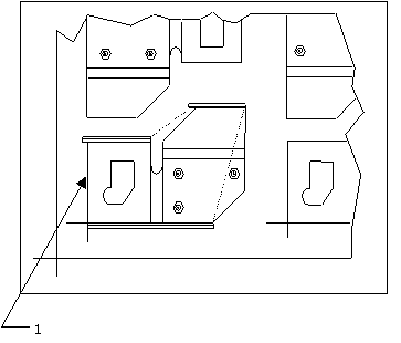
Machining Edges with Specified Orientation

1. The whole perimeter of the part is selected using loop. LOCKED_TOOL_ORIENT is set to 0.