Working with Schematic-Driven Pipeline Modeling
Use the sample files provided at <Creo load point>\Common Files\help\sample_models\piping when working in this exercise. It is recommended that you create a copy of the piping folder on your computer and set up piping data before you start working with the tutorial.
Workflow Diagram
1. Set up the configuration options.
2. Designate the schematic information.
3. Designate the equipment.
4. Create a pipeline in the Spec-Driven Piping mode.
5. Insert fittings using the schematic information.
6. Execute schematic consistency check.
Set up the Configuration Options
1. Open the piping folder and set the piping_assembly_schematic folder as the Working Directory.
2. Click >  Options > .
Options > .3. Select the piping_schematic_driven option and set its value to yes.
4. Select the piping_schematic_xml_dir option, click Browse, and select the XML folder.
5. Close the Configuration Editor.
Designate the Schematic Information
1. Open manifold_skid.asm.
2. Click >  Piping. The Piping tab opens.
Piping. The Piping tab opens.3. Click  Create Pipe. The Create Pipeline dialog box opens.
Create Pipe. The Create Pipeline dialog box opens.4. Under Schematic Driven, click  and double-click the from_schematic.xml file.
and double-click the from_schematic.xml file.Designate the Equipment
1. Click Designate. The Pipeline Designation dialog box opens.
2. Under Designate Equipment, select IC-2.
3. Select the Csys axis related to Port0.
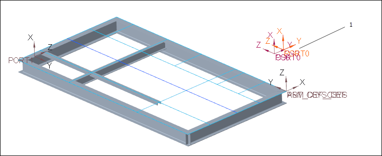
1. Csys axis
One Csys axis is automatically designated. There is only one remaining Csys axis that is matching the schematic details. |
4. Click  to commit the designation.
to commit the designation.5. Click >  Designation. The Pipeline Designation dialog box opens.
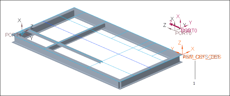
Designation. The Pipeline Designation dialog box opens.6. Expand the Model Tree and select 150A-MS-STEAM-LEG1.
The status of all the equipment in the Equipment tab is Designated and that of all the fittings in the Fittings tab is Missing. |
7. Click . The Pipeline Designation dialog box closes.
. The Pipeline Designation dialog box closes.Create a Pipeline in the Spec-Driven Piping Mode
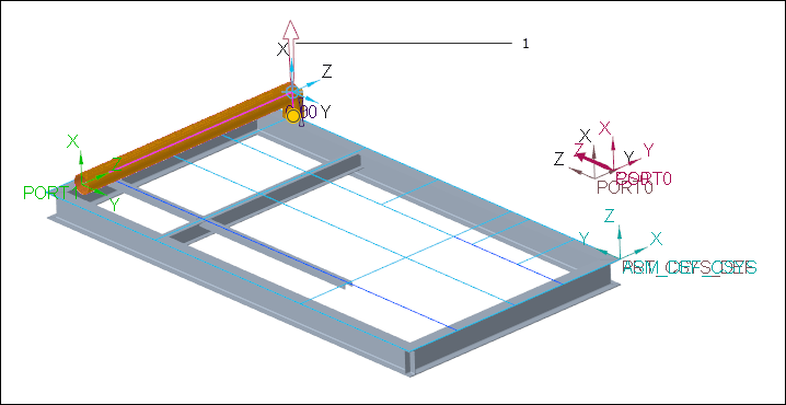
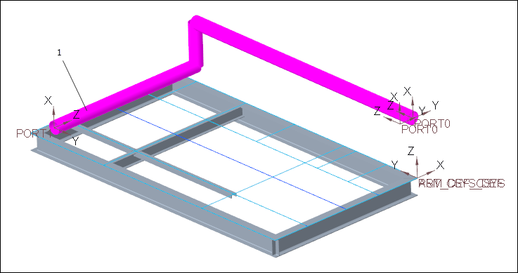
1. Click  Route Pipe and click
  Set Start. The Define Start dialog box opens.
Route Pipe and click Set Start. The Define Start dialog box opens.2. Select the Csys axis related to Port1.

1. Csys axis
3. Click OK. The Define Start dialog box closes.
4. Click  Extend. The Extend dialog box opens.
Extend. The Extend dialog box opens.5. Under Reference, select Along Csys Axis.
6. Under Dimension options, select Offset from Ref.
7. Select the Csys axis related to Port0 in the graphics window.
1. Csys axis
8. In the Dimension options box, type 0.00.
9. Click Apply. The first pipe segment is created.
10. Click  Environment. The Piping Environment dialog box opens.
Environment. The Piping Environment dialog box opens.11. In the Corner Type box, select Fitting.
12. Click OK. The Piping Environment dialog box closes.
13. In the Extend dialog box, select X axis.
14. Click the upward arrow to change the direction of pipe creation.
1. Upward arrow
15. Click Apply. The second pipe segment is created along the X-axis.
16. Click Cancel. The Extend dialog box closes.
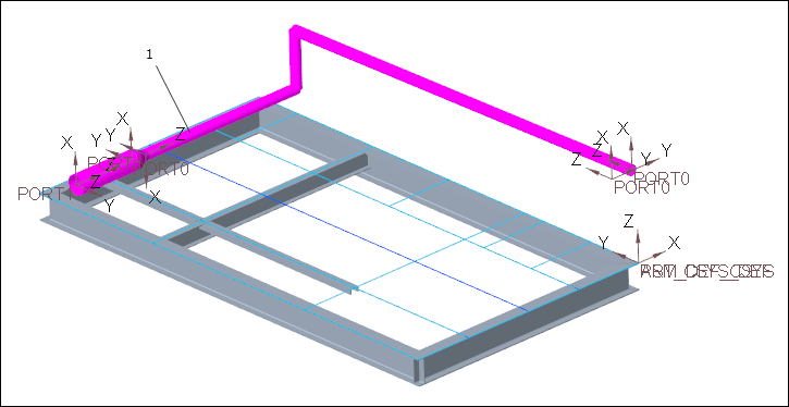
17. Click  To Pnt/Port. The To Point/Port dialog box opens.
To Pnt/Port. The To Point/Port dialog box opens.18. Select the Csys axis related to Port0 in the graphics window.
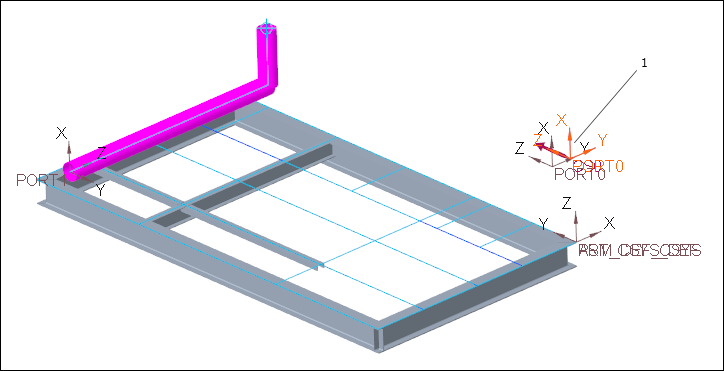
1. Csys axis
19. Click OK. The third pipe segment is created.
Insert Fittings using the Schematic Information
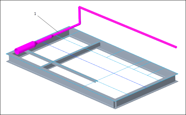
1. Click  Insert Fitting. The Insert Fitting dialog box opens.
Insert Fitting. The Insert Fitting dialog box opens.2. Select a location on the first pipe segment in the graphics window.
1. Location on the first pipe segment
3. Click Apply. A fitting is inserted on the pipe segment at the selected location.
The fitting is automatically selected from the schematic information. |
4. Select another location on the first pipe segment.
1. Location on the first pipe segment
5. Click Apply. The second fitting is inserted.
6. Click Cancel. The Insert Fitting dialog box closes.
Execute Schematic Consistency Check
1. Click  Piping Info. The Report Pipeline dialog box opens.
Piping Info. The Report Pipeline dialog box opens.2. Under Type, click  . The Schematic Consistency Check dialog box opens.
. The Schematic Consistency Check dialog box opens.3. Select 150A-MS-STEAM-LEG1 in the graphics window or on the Model Tree.
4. In the Select dialog box, click OK. The Select dialog box closes.
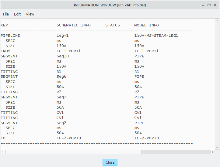
5. In the Schematic Consistency Check dialog box, click Apply. The INFORMATION WINDOW opens.
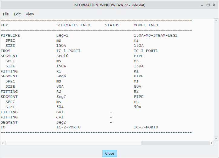
The INFORMATION WINDOW displays two missing fittings. These fittings appear to be mated together, because there is no pipe segment separating them. |
6. Close the INFORMATION WINDOW, the Schematic Consistency Check dialog box, and the Report Pipeline dialog box.
7. Click Group Fitting. The Insert Group Fitting dialog box opens.
Group Fitting. The Insert Group Fitting dialog box opens.8. Select a location on the first pipe segment.
1. Location on the first pipe segment
9. In the Insert Group Fitting dialog box, click  .
.
.10. Click the Placement / orientation tab.
11. Under Rotation angle, select 90.
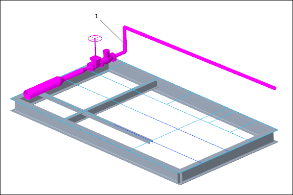
12. Click Apply. The fitting group is inserted at the selected location.
13. Click Cancel. The Insert Group Fitting dialog box closes.
14. Select the Gate valve in the graphics window and click  on the mini toolbar. The Redefine Fitting dialog box opens.
on the mini toolbar. The Redefine Fitting dialog box opens.
1. Gate valve
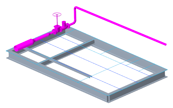
15. Under Rotation angle, select 90.
16. Click OK. The Gate valve rotates by 90 degrees.
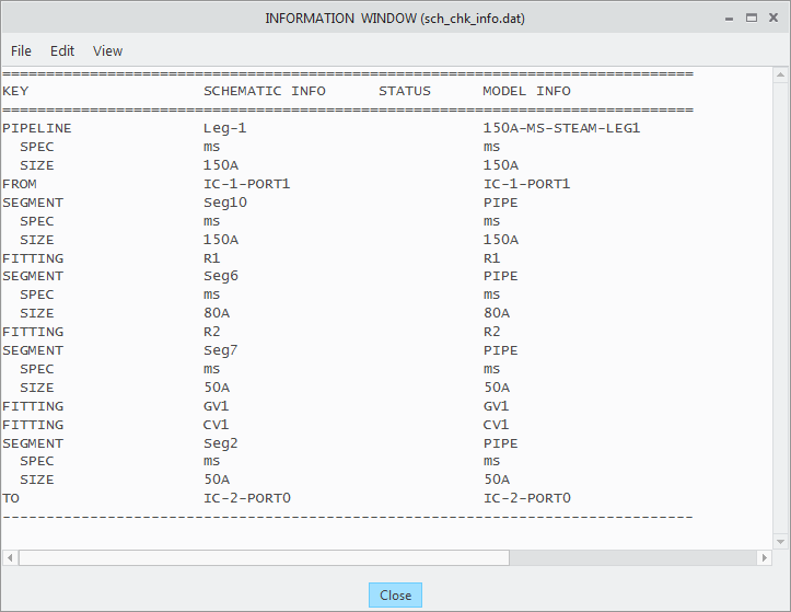
17. Repeat steps 1 through 5 to execute the schematic consistency check again. The INFORMATION WINDOW opens.
18. Close the INFORMATION WINDOW.
19. Click Insert Fitting. The Insert Fitting dialog box opens.
Insert Fitting. The Insert Fitting dialog box opens.20. Under Fitting, select  .
.
.21. Select the second pipe segment in the graphics window.
1. Second pipe segment
22. Select the At all corners box.
23. Click OK. The corner fittings are inserted.
24. Repeat steps 1 through 5 to execute the schematic consistency check again. The INFORMATION WINDOW opens.
Fittings, such as elbows or pipe hangers, are not normally listed in the schematic and are automatically ignored from the schematic consistency check. |
25. Close the INFORMATION WINDOW.