To Create a Draft Feature
This procedure describes the steps necessary to create a basic Draft feature. All other procedures for creating Draft features are based on this one.
1. Click >  Draft. The Draft tab opens.
Draft. The Draft tab opens.2. Click the  Draft surfaces collector, and select the surfaces to draft from a single body or a single quilt.
Draft surfaces collector, and select the surfaces to draft from a single body or a single quilt.
• You can also select one or more draft surfaces before entering the Draft tool. • You can also click Details on the References tab to open the Surface Sets dialog box to collect surfaces. • You can select open surfaces as draft surfaces. An open surface is a surface that has at least one one-sided edge. |
3. To select the draft hinge, click the  Draft hinges collector, and select a chain of edges or curves, or a plane, quilt, or round or chamfer surface that the draft surfaces pivot about.
Draft hinges collector, and select a chain of edges or curves, or a plane, quilt, or round or chamfer surface that the draft surfaces pivot about.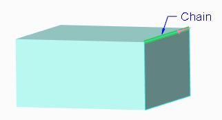
If you do not have a plane, quilt, or curve to use as a draft hinge, you can pause the Draft tool and create one asynchronously, then resume the Draft tool. |
4. To set the pull direction, click the Pull direction collector on the References tab, and select a plane (in which case the pull direction is normal to this plane), a straight edge, a datum axis, or an axis of a coordinate system. The pull direction is the direction you would pull the part out of a mold.
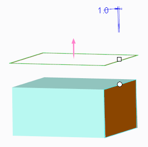
The pull direction is indicated with an arrow, and the preview geometry for a constant draft with the default angle is shown. The default draft angle value is displayed in the graphics window and in the  Angle 1 box. Two drag handles are also shown. One is located on the draft hinge or on the draft surface contour, and one is connected to the draft angle.
Angle 1 box. Two drag handles are also shown. One is located on the draft hinge or on the draft surface contour, and one is connected to the draft angle.5. To modify the draft angle, type or select a value in the Angle 1 box. You can also drag the handle connected to the draft angle, or double-click the draft angle value in the graphics window and type or select a value.
Angle 1 box. You can also drag the handle connected to the draft angle, or double-click the draft angle value in the graphics window and type or select a value.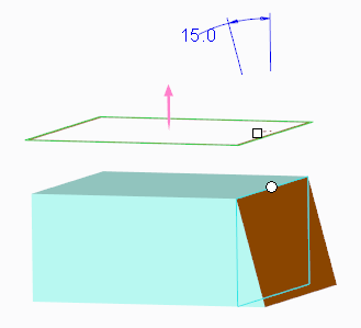
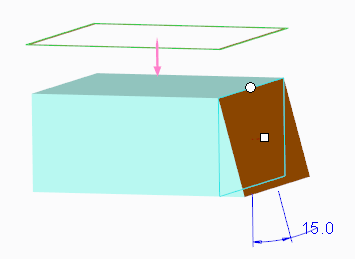
6. If needed, to flip the draft angle, click  to the right of the Angle 1 box to add or remove material. You can also drag the handle connected to the draft angle to the other side of the part surface to which it is attached, or type a negative draft angle value.
to the right of the Angle 1 box to add or remove material. You can also drag the handle connected to the draft angle to the other side of the part surface to which it is attached, or type a negative draft angle value.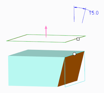
7. If needed, to flip the pull direction, click the pull direction arrow in the graphics window. You can also click Flip on the References tab.
Flipping the pull direction affects the direction of the draft angle, and the order of the sides in a split draft. |
8. Use other options in the Draft user interface to create more complex draft geometry, if necessary. For more information, refer to the Related Links.
9. Click  OK.
OK.
OK.