Example: Creating a Unidirectional Linear Pattern
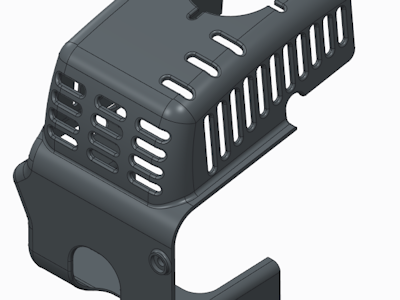
This example shows creating a unidirectional pattern of holes. The original part is shown in the following image.
1. Select the slot feature and click >  Pattern. The dimensions that control the selected feature are displayed.
Pattern. The dimensions that control the selected feature are displayed.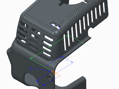
2. Select the dimension with the value of 77, which controls the distance from the slot to the edge of the part, as shown in the next image.
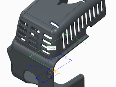
3. A value box opens in the graphic window, with the dimension increment initially equal to 77 (the dimension value). Type –20 for the dimension increment.
4. To specify the number of pattern members in the first direction, type 3 in the Members box on the Pattern tab.
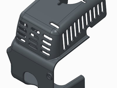
5. Click  OK. The system patterns the slot, as shown in the following illustration.
OK. The system patterns the slot, as shown in the following illustration.