Example: Creating a Bidirectional Linear Pattern
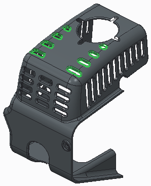
This example shows creating a bidirectional pattern. The original part is shown in the following image.
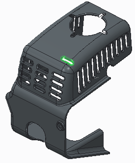
1. Select the slot and click >  Pattern. The dimensions that control the selected feature are displayed.
Pattern. The dimensions that control the selected feature are displayed.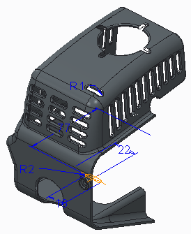
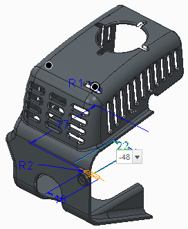
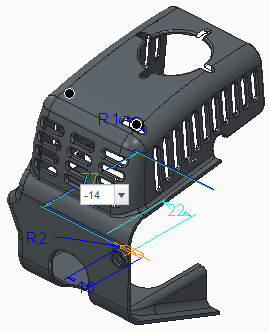
2. To set the increment for the first direction, select the dimension with the value of 22. A value box opens in the graphic window, with the dimension increment initially equal to 22 (the dimension value). Type -48 for the dimension increment.
3. To set the number of pattern members in the first direction, type 2 in the Members box on the Pattern tab.
4. To pattern the second direction, click the Dimensions tab, and click the Direction 2 collector. Select the dimension with the value of 77. Type -14 for the dimension increment.
5. To specify the number of pattern members in the second direction, type 4 in the Members box on the Pattern tab.
6. To also change the slot length in the second direction of the pattern, click the Direction 2 collector on the Dimensions tab. Since there is already one dimension in the collector, hold down the CTRL key and select the slot length dimension with the value of 16. Type -3 for the dimension increment.
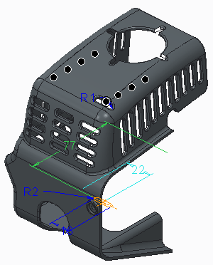
7. Click  OK. The pattern is created, as shown in the following figure.
OK. The pattern is created, as shown in the following figure.