To Create a Helical Sweep
1. On the Model tab, click the arrow next to  Sweep, and click
  Helical Sweep. The Helical Sweep tab opens.
Sweep, and click Helical Sweep. The Helical Sweep tab opens.2. Select or sketch the helix profile:
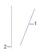
1. Helix profile
2. Helix axis
◦ To select a sketch, click the References tab, click the Helix profile collector, and then select an open sketch.
◦ To sketch a profile:
1. Click the References tab, and click Define. The Sketch dialog box opens.
2. Set the sketch plane and orientation, and then click Sketch. The Sketcher opens.
3. Sketch the helix profile. You can define the profile using an edge or offset. When sketching, follow these rules:
▪ The sketch must be open (sketched entities cannot form a loop).
▪ If you select Normal to trajectory for the section orientation, the helix profile entities must be tangent to each other (C1 continuous).
▪ The helix profile entities must not have a tangent that is normal to the centerline at any point.
4. To include the axis of revolution in the sketch, click >  Centerline in the Datum group, and sketch a geometry centerline to use as the axis of revolution.
Centerline in the Datum group, and sketch a geometry centerline to use as the axis of revolution.5. Click  OK to exit Sketcher.
OK to exit Sketcher.3. To toggle the start point of the helical sweep from one end of the helix profile to the other end, click Flip next to Start point.
4. To select the helix axis of revolution, do one of the following actions, depending on whether the helix profile sketch contains a geometry centerline:
◦ Sketch does not contain a geometry centerline—Click the Helix axis collector, and select a straight curve, edge, axis, or axis of a coordinate system in the graphics window or Model Tree. The selected reference must lie on the sketch plane.
◦ Sketch contains a geometry centerline—The geometry centerline is selected as the axis of revolution, and InternalCL appears in the Helix axis collector.
If InternalCL does not appear in the Helix axis collector, click Internal CL to use the centerline in the sketch.
5. Sketch the section of the sweep:
a. On the Helical Sweep tab, click  Sketch. The Sketch tab opens.
Sketch. The Sketch tab opens.b. At the sweep start point (crosshair intersection), sketch a section to sweep along the trajectory. The sweep section, the helix profile, and the crosshair intersection should all be on the same side of the axis of revolution.
c. Click OK. The Sketch tab closes.
OK. The Sketch tab closes.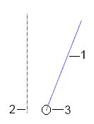
1. Helix profile
2. Helix axis
3. Sweep section
6. To set the section orientation, on the References tab, under Section orientation, select one of the following options:
◦ Through helix axis—Orients the section to pass through the helix axis.
◦ Normal to trajectory—Orients the section to be normal to the helical trajectory.
7. To create a curve from the helical trajectory, so that the curve will be available in Creo after the helical sweep is created, select the Create helical trajectory curve check box.
8. Click  Solid to create the sweep as a solid or
  Surface to create it as a surface.
Solid to create the sweep as a solid or Surface to create it as a surface.9. To remove material along the helical sweep, click  Remove Material, and then perform actions depending on whether it is a solid or surface feature:
Remove Material, and then perform actions depending on whether it is a solid or surface feature:◦ Solid
Solid▪ Optionally, click  to flip the side of the sketch from which material is removed.
to flip the side of the sketch from which material is removed.◦ Surface
Surface1. Click the Quilt collector, and then select a quilt to trim.
2. To change the portion of the quilt to be removed, click  to the right of Remove Material. Switch between three modes:
to the right of Remove Material. Switch between three modes:▪ Remove side 1
▪ Remove side 2
▪ Keep both sides
10. If you keep both sides of the quilt, to select the side that will inherit the original quilt ID, click to the right of the Quilt collector.
to the right of the Quilt collector.11. To give the sweep a thickness, click  Thicken Sketch, and then type or select a thickness value. Use to switch the thicken direction between one side, the other side, or both sides of the sketch.
Thicken Sketch, and then type or select a thickness value. Use to switch the thicken direction between one side, the other side, or both sides of the sketch.12. To set the pitch, the distance between the coils of the helix, do one of the following:
◦ Constant pitch—Next to , enter a pitch value.
, enter a pitch value.◦ Variable pitch—Click the Pitch tab to add, define, and place pitch points as needed.
For more information, see To Set the Pitch in Helical Sweeps and Volume Helical Sweeps.
13. To trim a quilt when Surface and Remove Material are selected, click the Quilt collector, and select a quilt to trim.
Surface and Remove Material are selected, click the Quilt collector, and select a quilt to trim.a. Click to the left of the Quilt collector to switch the side of the quilt to remove between one side, the other side, or both sides of the quilt.
to the left of the Quilt collector to switch the side of the quilt to remove between one side, the other side, or both sides of the quilt.b. If you keep both sides of the quilt when you trim it, click to the right of the Quilt collector to toggle between two sides of a quilt to specify which side retains the quilt ID.
to the right of the Quilt collector to toggle between two sides of a quilt to specify which side retains the quilt ID.14. Click  Left-handed Rule to use the left-handed rule, or click
  Right-handed Rule to use the right-handed rule.
Left-handed Rule to use the left-handed rule, or click Right-handed Rule to use the right-handed rule.Left-handed Rule | Right-handed Rule |
|---|---|
 |  |
15. To specify whether the section remains the same or varies, on the Options tab, under Along trajectory, select an option:
◦ Constant—Maintains a constant section as it sweeps along the trajectory.
◦ Variable—Creates a sweep with a variable section. Uses section relations with the trajpar parameter to make the sketch variable. The sketch regenerates at points along the origin trajectory and updates its shape accordingly. For more information about using the trajpar parameter, see About the Trajpar Parameter.
16. To close the ends of a surface sweep, on the Options tab, select the Capped ends check box.
Capped ends is available for surface sweeps with a closed section and an open trajectory. |
17. For solid features, click the Body Options tab, and then select the body to which to add geometry, or from which to remove geometry:
◦ Add geometry
▪ To add geometry to an existing body, click the body collector, and then select the body to which geometry is added.
▪ To create the feature in a new body, select the Create new body check box. The name of the new body appears in the body collector.
◦ Remove geometry
▪ To cut geometry from all the bodies that the feature passes through, select All.
▪ To cut geometry from selected bodies:
1. Select Selected.
2. Click the body collector, and then select bodies from which to cut geometry.
18. Click  OK.
OK.
OK.