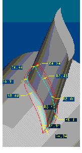
Example: Using a Measurement in a Relation
Summary—This example shows you how to use an analysis feature to create a dependency between the geometry of a rotor blade and the rounds added at the edges where the blade is attached to the rotor.
Problem—In this model, the geometry of a blade is controlled by three graphs, one for each direction. A round is created along the edges of the blade where it is attached to the rotor. When you change a graph, the geometry of the blade is updated. However, this change may cause rounds created at the edges to fail due to a conflict in the radius values.
Solution—You can relate the geometry of the round to the angle between the blade and the rotor. Do this by creating an analysis feature that measures the dihedral angle at several points along the edge where the blade is attached to the rotor. Then you can create a round and define the radius value at each point as a function of the measured dihedral value. The resulting round is driven by the dihedral angle. Each time you modify the geometry of the blade and the dihedral angle changes, the geometry of the round is updated to reflect new radius values.
The following basic steps outline this example:
1. Open a part BLADE and create datum points at the locations where you want to specify different radius values for the round.
2. Measure the dihedral angle between the rotor and the blade at the selected datum points by creating an analysis feature at each point. In the Point dialog box, specify the following:
a. Enter the name of the analysis, analysis1
b. Under Type, select Feature and select a datum point.
c. Click Definition. The selected point appears in the Point box.
d. Click Feature. The Parameters table and the Datums table on the Point dialog box display the associated parameters and datum points with their details under Create, Name and Description.
e. Click NO against the name of the parameter in the Parameters table. The selected parameter is created.
f. Click  . The analysis feature is created.
 . The analysis feature is created.
3. Create an advanced round at the attachment edge with variable radius values. When specifying the radius value for each datum point, enter a relation in the following format:
K * measurement_name:fid_analysis_name where,
◦ K–Coefficient you specify.
◦ measurement_name—Name of a measurement, for example, dihedral
◦ analysis_name—Name of the analysis feature for the selected datum point, for example, analysis1
For the first point selected, a relation may appear as 0.1 * dihedral:fid_analysis1
4. Finish creating the round. This round is driven by the current value of the dihedral angle. When you change the graph that controls the blade, Creo Parametric recomputes the values of the dihedral angles and rebuilds the round accordingly.
The next figure shows an example part.

The next figure illustrates datum points at which the dihedral angle is measured.

The next figure shows how a round is created.
