Analysis Results
You can view and manage the creepage and clearance computation results in the Results tab.
1. In the Source list, select a source. You can select only those sources for which the clearance and creepage computation was performed.
2. Under Target Net, you can view all the targets for which a distance value greater than 0 is specified with respect to the selected source. All the targets display icons for creepage and clearance. The icons indicate the type of violation between the source-target pair:
◦  — A major violation. The path distance is less than the clearance distance or creepage distance.
— A major violation. The path distance is less than the clearance distance or creepage distance.◦  — A minor violation. The path distance is less than the addition of clearance distance and violation tolerance or creepage distance and violation tolerance.
— A minor violation. The path distance is less than the addition of clearance distance and violation tolerance or creepage distance and violation tolerance.◦  — No violation. The path distance is more than sum of the clearance distance and the violation tolerance or creepage distance and the violation tolerance.
— No violation. The path distance is more than sum of the clearance distance and the violation tolerance or creepage distance and the violation tolerance.◦  — No computation was performed for the respective source and target. This icon is visible if a computation is performed on a single source using the Analysis tab.
— No computation was performed for the respective source and target. This icon is visible if a computation is performed on a single source using the Analysis tab.◦  — No violation, but a shortest path is available. There is no path within the sum of the specified distance and violation tolerance, but the shortest path between the net pair is available due to the value set in the Maximum Search Distance for Shortest Path box.
— No violation, but a shortest path is available. There is no path within the sum of the specified distance and violation tolerance, but the shortest path between the net pair is available due to the value set in the Maximum Search Distance for Shortest Path box.3. Click a path in Target Net list to view details of the paths between the source and target listed in the Clearance and Creepage columns. All paths between the corresponding source and target pair are visible in the path list in the ascending order. You can analyze the paths as follows:
◦ Click All Paths under the Clearance and Creepage columns to simultaneously view all the paths. All the path distances are rounded to two decimal places in the result list.
◦ Click a path under the Clearance and Creepage columns to view it in the graphics window. Under Path Info, you can see the exact value of the selected path.
Path Information
Under Path Info you can view the general information about the selected path, including the information listed below:
• The source and target net and the intermediate nets through which the path takes a shortcut.
• The violation distance that accounts for the path. The groove width is displayed for creepage path.
• The exact length of the path. The creepage path also shows the CTI value of the insulator on which the path travels.
• Additional comments.
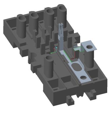
The following image shows the path information and identification or documentation details for a path.

To Review a Path
You can perform the following operations to document or to identify the path:
• Right-click a path and select Remove to permanently remove the path.
• Right-click a path, select Set Tag, and then select one of the following tags listed in the table below. Setting a tag helps to identify the paths that are verified and to provide information about the state of the current analysis.
Tag | Description |
|---|---|
 OK OK | This path does not have any violations. |
 Violation Violation | The path is causing a violation and you need to revise the assembly. |
 Unknown Unknown | Not sure about the path. |
• When you tag a path the corresponding icon appears next to it. Manually tagging a path as OK may change the violation indicator for the respective net pair in the target list. If all the paths in a column are manually set to OK, the icon for no violation  appears for the net pair. The orange dot indicates that the no violation indication is due to manual overrides of the violating paths.
OK may change the violation indicator for the respective net pair in the target list. If all the paths in a column are manually set to OK, the icon for no violation appears for the net pair. The orange dot indicates that the no violation indication is due to manual overrides of the violating paths.• You can add comment for a path in the Comment box under Path Info. An orange dot  appears next to the commented paths. The Comment box is editable and you can update the comment.
appears next to the commented paths. The Comment box is editable and you can update the comment.• Click a path to view it in the graphics window. If the path is covered by several components, it may be difficult to identify the exact path location. Use the following options to zoom to the start and the end of the path:
◦ Click Zoom to Start Point to zoom to the start of the selected path.
◦ Click Zoom to End Point to zoom to the end of the selected path.
• Select the Show Involved Only check box to automatically hide the components that are not included in the selected path. The visible elements are reduced to the selected source and target components, and all insulators that the path touches. See the following example.
Show Involved Only check box cleared | Show Involved Only check box selected |
 |  |
Highlighting Source and Target
If you select this option, the included surfaces of the source and target net that corresponds with the current path are highlighted.
Exporting a Violation Matrix
Click  to export the violation matrix to an .xlsx file. The violation matrix provides an overview of the types of violation and the shortest distance for all net pairs in the model.
to export the violation matrix to an .xlsx file. The violation matrix provides an overview of the types of violation and the shortest distance for all net pairs in the model.The following image shows the violation matrix for all net pairs for an assembly:

In the violation matrix, the cells are color-coded to indicate the severity of the violation, as follows:
• — Major violation.
— Major violation.• — Minor violation.
— Minor violation.• — No violation.
— No violation.• — No violation, but a shortest path is available.
— No violation, but a shortest path is available.You must have an application like Microsoft Excel to open the violation matrix .xlsx file. |