Isolines Surface Milling
For Surface milling from surface isolines, the machining direction is defined by the natural u-v contour of the surface to be milled. If the surface to machine is at an angle with the coordinate system axes, you may want to use the From Surface Isolines option rather than Conventional Milling.
Isolines Surface Milling NC sequences generate the tool path which will:
• Completely machine the selected surface(s). If a surface is not bounded by walls on the outside, the tool will "straddle", that is, overrun the surface boundary by a half diameter.
• Any inner protrusions, as well as the outer walls extending up from the surface, will be avoided automatically. The stock allowance, if any, will apply to the side walls as well.
• Internal holes and slots will not be "patched". For 3-Axis milling, the tool will move over internal slots or holes at a constant Z level, plunging or retracting at the lower edge as necessary. For 4- and 5-Axis milling, the tool will retract at all inner edges. If you don’t want this to happen, use a Mill Surface, or select a surface from a Mill Volume.
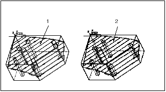
The following illustration shows using a Mill Surface for Isolines Surface Milling.

1. Select part surface
2. Select a Mill Surface created using Copy and >
If you select more than one surface, the surfaces must allow for a continuous tool path. Each surface will be machined separately. You will be able to specify the machining direction independently for each of the selected surfaces. You will also be able to specify the order in which the surfaces will be milled.
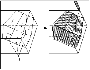
The following illustration shows specifying machining direction for multiple surfaces. Surfaces (1) were selected to change machining direction.
