Example: User Defined Tool Parameters
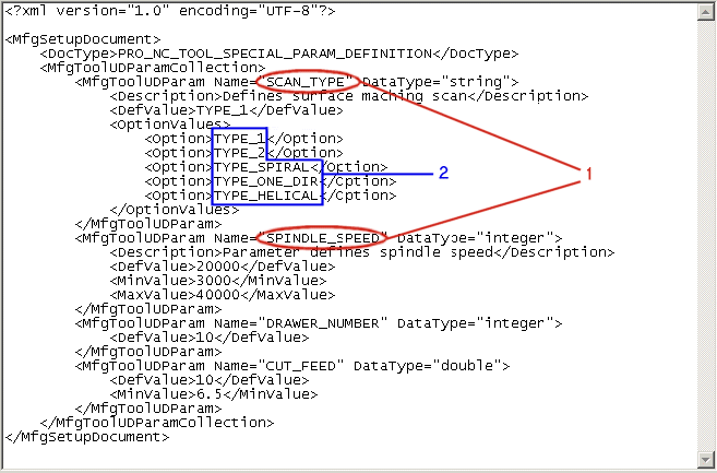
In the following example, a user defined parameter file is used to customize the used defined parameters in the Tools Setup dialog box. The contents in the user defined parameter file are organized as follows:

1. The name of the user defined parameter.
2. The values to be displayed for the given parameter in the User Defined tabbed page in the Tools Setup dialog box.
1. Set the mfg_custom_tool_param_file configuration option to point to the path where the tool parameter file is stored.
2. Click  on the top toolbar. The Tools Setup dialog box opens. If the tool parameter file you specified using the mfg_custom_tool_param_file configuration option exists and is syntactically correct, an additional tabbed page—User Defined, is added at the end of the existing tabbed pages in the Tools Setup dialog box.
 on the top toolbar. The Tools Setup dialog box opens. If the tool parameter file you specified using the mfg_custom_tool_param_file configuration option exists and is syntactically correct, an additional tabbed page—User Defined, is added at the end of the existing tabbed pages in the Tools Setup dialog box.
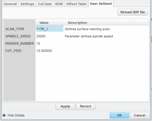
3. Click the User Defined tabbed page. The parameters defined in the tool parameter file are parsed and displayed by Creo NC as shown below:

You can specify a value for each parameter. However, the values you specify in the User Defined tabbed page for each parameter must be in accordance with the restrictions imposed, if any, for that parameter in the user defined parameter file. For example, in the user defined parameter file above, the parameter SPINDLE_SPEED can have a minimum value of 3000 and maximum value of 40000. If the value you enter is less than 3000 or greater than 40000, Creo NC displays an error message.
If you want to add or delete parameters or modify one or more existing parameters, you can do so only in the user defined parameter file. After making the necessary modifications, save the file. In the User Defined tabbed page in the Tools Setup dialog box, click Reload UDP file button. The modifications you made to the user defined parameter file are updated in the User Defined tabbed page.