About ECAD in the Design Process
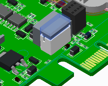
ECAD lets you import data for printed circuit boards and PCB components into an assembly. After importing, you can view the board and parts in a 3D context, for example, the PCB within the metal case that contains it.
Alternatively, the board outline dimensions can be established in Creo Parametric, based on the case assembly, and exported for parts placement and routing in ECAD.
With ECAD, you can edit certain physical aspects of the board, for example, component positions, keepout areas or mounting holes, and export the edited board back to the original ECAD package.
You can also:
• Use custom-designed component models, based on part outlines imported from your ECAD design, that represent the 3D shape of components more accurately.
• Use Assembly commands (or information from the ECAD package) to pre-place certain critical components.
Creo Parametric does not import trace or connectivity data to ECAD. It deals with the three-dimensional shape and placement of components only. |
Creo ECAD-MCAD Collaboration
The Creo ECAD-MCAD Collaboration mode is available in the standard assembly mode of Creo Parametric. It provides the collaborative environment for Creo Parametric, and Creo View ECAD. Creo Parametricand ECAD application users can propose and share design changes in this collaborative environment.
To initiate the collaboration effort from Creo Parametric, with an ECAD assembly open, you must click  ECAD Collaboration.
ECAD Collaboration.