About Creating Cuts
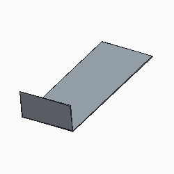
A cut removes material from your part. The cut is made normal to the surface, as if the part were completely flat, even if it is in a bent state. The cut adopts the natural behavior, like bending and warping, when the part is bent.
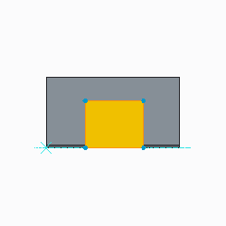
You sketch cuts on a plane and projects them onto the board segment. The driving side, offset side, or both driving and offset sides of the board segment can determine the cut direction.
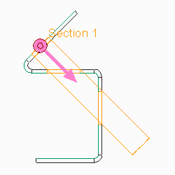
• Solid Cut
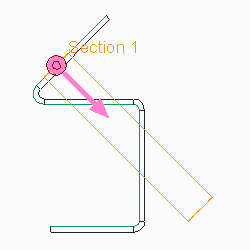
• Cut Normal to both Driving and Offset Surfaces
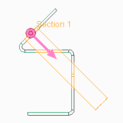
• Cut Normal to Driving Surface
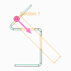
• Cut Normal to Offset Surface
You can create three types of cuts:
• Board Segment Cut (solid)—Removes solid sections of material.
• Board Segment Cut (thin)—Removes only a thin section of material, like a thin cut made with a laser.
• Solid Cut—Removes solid sections of the board segment. You can extrude, revolve, sweep, blend, use quilts and make advanced solid cuts. To make a defined-angle cut, you must use the solid cut. Solid cuts can be made on an edge. See the Part Modeling Functional Area for information about solid cuts.
Always use the Board Segment solid cut, unless you need tapered edges. |
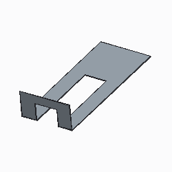
Because board segment cuts are surface cuts, you cannot make a cut to partially remove thickness. For example, you cannot cut a 1 cm deep hole in a 10 cm thick. The Blind depth command applies to cutting on bends. You can sketch the cut to the edge of the bend and project it a blind depth down the bent segment, saving you the time of unbending the segment, making the cut, and bending back the segment.
• Original Bent Segment
• Blind Cut Sketch
• Blind Cut
• Cutting on angles or bend areas might require a larger dimension scale for proper clearance. • Cuts can be used to create notch and punch UDFs. |