Modifying Locations
To Redefine a Location
1. Do one of the following:
◦ Right-click the location in the Model Tree and choose  from the shortcut menu. The Location tab opens.
from the shortcut menu. The Location tab opens.◦ Select a location in the Locations list in the Items tab.
◦ Select a location in the graphics window, right-click, and choose .
.2. Make the changes required and click  .
.
.When you edit the definition of a location the segments passing through the location display as read only in the Included Items list. The Placement and Options tab collectors available can be edited. A drag handle appears on the location when you can change the position.
To Modify Location Properties
1. Select one or more locations in the Model Tree or graphics window.
2. Click  Properties. The Location Properties dialog box opens. Alternatively, you can click Properties and then select the locations. The selected locations are displayed in the Location Properties dialog box.
Properties. The Location Properties dialog box opens. Alternatively, you can click Properties and then select the locations. The selected locations are displayed in the Location Properties dialog box.Only properties you can change are available. |
3. Modify the any of following properties.
◦ Grouping—Sets the grouping to Flat or Round.
◦ Angle—Determines the packing angle.
◦ Max Diameter—Determines the maximum diameter of items routed through the location. Values allowed are None to remove the parameter or values from 0 to 1e+6. This value constrains the cable thickness at the selected locations.
◦ Segment Shape—Sets the segment shape to Smooth or Straight.
◦ Priority—Sets the priority level for network locations to one of the following:
▪ Primary—High priority when routing via a network.
▪ Required—Must be utilized when routing via a network.
▪ Secondary—Reduced priority for routing via a network.
▪ Disallowed—Must not be used for routing via a network.
When multiple locations are selected, they can have different property values. When a property has different values it is considered undefined. Assigning a value will affect all selected locations. |
4. Click OK.
To Modify Packing at Locations
1. Click > .
2. Select a flat location with more than one cable to modify the packing. The Modify Packing dialog box opens.
A ribbon cable appears as a single entry in the Modify Packing dialog box, regardless of the number of conductors in the cable. |
3. Modify the Cable name or Thickness and set the other settings appropriately.
You can cut and paste items in the list of items at that location to modify the shape of the flat grouping.
4. Use the buttons for the following options
◦ New Row—Creates a new row after the selected row.
◦ Merge Rows—Merges two rows.
◦ Cut—Removes the selected row.
◦ Paste After—Places the removed row after the selected row.
◦ Paste Before—Places the removed row before the selected row.
◦ Default—Restores the default packing for the location.
◦ Copy—Copies packing from another locations. At the prompt select a location to copy packing.
5. Specify the Justification as follows:
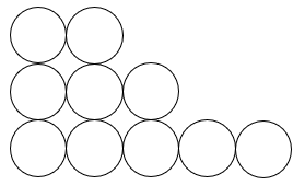 |  | 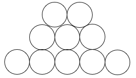 |
Left justification | Right justification | Center justification |
6. Click Apply to preview the visual changes to the packing in your assembly.
7. Click OK to make the changes permanent and close the dialog box.
To Modify the Size of Location Nodes in Drawing
1. In an open drawing, click > > . The Drawing Properties dialog box opens.
2. Click change in the Detail Options line. The Options dialog box opens.
3. Specify a value in drawing units of the location_radius setting. This sets the radius of the nodes displayed. You can specify the word DEFAULT as the value of this setup option. The default value is 2.
4. If you specify the setting as 0.0, the location nodes are displayed, but do not print.
Modifying the size of the location nodes is helpful when printing drawings. |
To Remove Locations
1. Click  Remove Locations. The LOC REMOVE menu appears.
Remove Locations. The LOC REMOVE menu appears.2. Click ItemFromLocs to remove a single item from multiple locations. Select a location to remove. If you select a location at a branch, Creo Parametric identifies a segment, and the SELECT SEG menu appears. Click OK, choose the second location at the end of the selected segment to delete both the locations, and click Yes at the prompt to accept the changes. To remove a single location, select the location and middle-click. The location is removed.
or
Click ItemsFromLocs to remove multiple items from multiple locations. Use the SEL CABLES menu to select all the items passing through the selected locations and click Done Sel. Select another location and click OK in the Select dialog box. To remove the items and the locations, you are prompted to click Yes.
Any locations except a direction or connector location can be removed as long as at least two locations remain to define a cable segment. A location with children cannot be removed. |
To Change a Location Reference
1. Select a location to redefine, click . The Location tab opens.
. The Location tab opens.2. Click Placement. The Placement tab opens.
3. Select a reference to remove, right-click and click Remove from the shortcut menu.
4. Select a new reference for the location.
5. Click .
.