Harness Related Report Table Parameters
You can use several report parameters in Cabling, cabling assemblies and flat harnesses. You can also use an item's parameters as user-defined parameters in a report table.
Perform the following steps to set the model before creating a table. Using this table, you can access the report parameters.
1. Open the required drawing and click  Drawing Models. The DWG MODELS menu appears.
Drawing Models. The DWG MODELS menu appears.2. Click Add Model to add a new part or assembly to the drawing. The selected model becomes the default or current model.
3. If you have added multiple parts or assemblies, click Set Model to set the required harness part or flat assembly as the current model.
The report parameters in the following table use cond to refer to all wires and cable conductors in a harness and run to refer to all wires and cables in a harness. The term from/to indicates that the parameter exists for both From and To directions. The User Defined category indicates that you can specify user-defined parameters and also system parameters.
For example, although &harn.run.spool.color is not specifically defined, you can specify &harn.run.spool.UserDefined and type the system parameter color.
The following conditions apply:
Report Parameter | Active Model | Attribute |
|---|---|---|
&harn... | Harness part | NA |
&asm.mbr.cblprm(s)... | 3D assembly | Cable Info |
&asm.mbr.connprm... | 3D assembly/Flat assembly | NA |
The Cable Info attribute is available only when you select at least one cable parameter in the repeat region. |
To assign a different model to a region:
1. Select a cell in the table and click Repeat Region. The TBL REGIONS menu appears.
2. Click Model/Rep to display a different model or simplified representation to control a region. If you change the model associated with the repeat region, the repeat region is populated with the respective data.
3. Select a region. The Open dialog box opens.
4. Select a new part or assembly to be associated with the repeat region.
Location of User Defined Pin Parameters
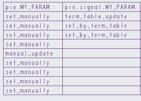
In a drawing report table, user defined pin parameters created by importing logical data or executing terminator tables are displayed in pin.signal.UserDefined column.
In the above example, the user defined pin parameter MY_PARAM that is created either by logical data or by execution of a terminator table is displayed in pin.signal.MY_PARAM. The user defined pin parameter MY_PARAM that is created manually is displayed in pin.MY_PARAM.
User defined pin parameters that are added manually in Electrical Parameters dialog box or automatically created by logical data or by execution of a terminator table are displayed in the Electrical Parameters dialog box under a single column allotted for user defined parameters under Pins. For example, in the following example, the user defined pin parameter MY_PARAM and values are displayed in the MY_PARAM column under Pins.
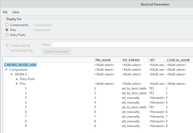
In Electrical Parameters dialog box, for the parameters created by importing logical data or executing terminator tables, the SET column displays YES and for manually created parameter the column displays <Nonexistent>. |
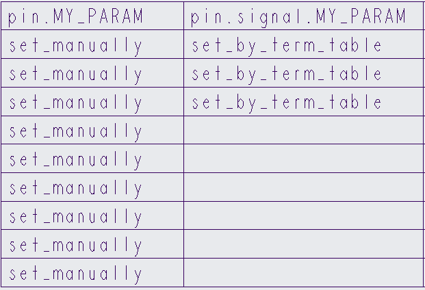
In a drawing report table, the user defined parameters are displayed in two separate columns. For example, pin.MY_PARAM and pin.signal.MY_PARAM. Two separate columns are used to display the user defined parameters in a a drawing report table despite the fact that the user defined parameters are combined together and displayed in a single column in the Electrical Parameters dialog box.
In the Electrical Parameters dialog box, if you change the value of MY_PARAM on any of the pins by importing logical data or executing terminator tables, the pin.signal.MY_PARAM column in the drawing report table is updated.
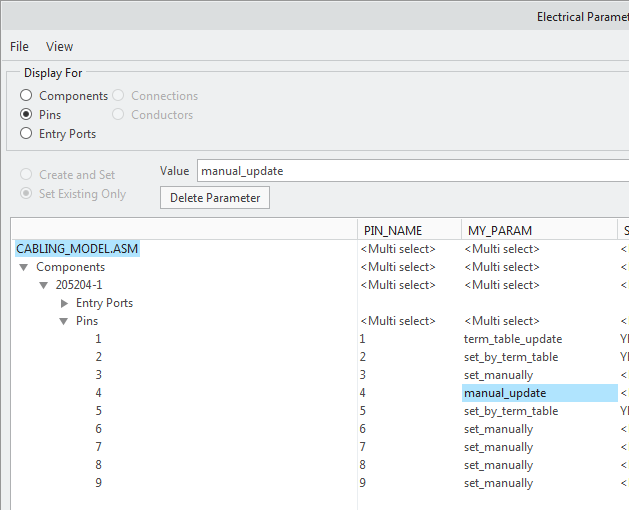
In the Electrical Parameters dialog box, if you manually set the value of MY_PARAM on any of the pins, the pin.MY_PARAMcolumn in the drawing report table is updated accordingly.