Assigning Location Priority for Network Locations
To control how cables are automatically routed along a network, you can assign priorities to network locations.
To Assign Location Priority
1. Select the location in the graphics window or Model Tree and click  Properties. The Location Properties window opens.
Properties. The Location Properties window opens.2. From the Priority list, select one of the following options:
Type | Description |
|---|---|
Primary (Default) | These network locations are used whenever possible. |
Required | Forces all wires being routed via a network to pass through the specified location or locations in the same direction, even if this does not create the shortest path for each wire. This priority is used to handle wires that are routed through a common splice or to a splice that is to be inserted. You can also use this priority to ensure that wires travel through a specific hole or duct. |
Disallowed | Disallowed network locations cannot be used for routing via a network. You can use this property to avoid overfilling of channels, interference with a fixed size hole in a bulkhead, or creation of loops in an individual harness. |
Secondary | A network location that is used for automatic routing only if no complete path using primary locations is available. |
3. To set required locations to find the shortest path, click  Priority > . The REQD LOCS menu appears.
Priority > . The REQD LOCS menu appears.4. Select one of the following check boxes:
◦ Optimize—Optimizes the shortest path with at least one location for all cables routed via the network.
◦ Put On Wire—Finds the shortest paths with a common location on the selected wire.
To learn how to assign a location priority to an assembly, go to Exercise - Assigning Location Priority
5. To reset the priority of all locations, click > .
Modifying the location priority only affects subsequent route via network operations. Wires that are already routed are not affected. |
To Modify Network Locations
1. Open the Locations tab using one of the following methods:
◦ Select the network or network segment in the Model Tree or graphics window, right-click, and click  from the shortcut menu.
from the shortcut menu.◦ Select a network location in the Model Tree or graphics window, right-click, and click  from the shortcut menu.
2. You can move the location, change placement references, and change the grouping and the packing angle.
3. Click  .
.
.• When a network has dependent locations and assembly references are updated, the network shape is updated too. • To delete a network segment, select it in the graphics window or Model Tree, right-click, and click Delete from the shortcut menu. If you delete a network, the cable locations remain and the color of the cable or network changes. |
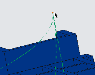
To Define the Tangency Direction at Network Branches
1. Click  Fix Tangency to set the tangency between the network and branch.
Fix Tangency to set the tangency between the network and branch.2. When prompted, select a location.
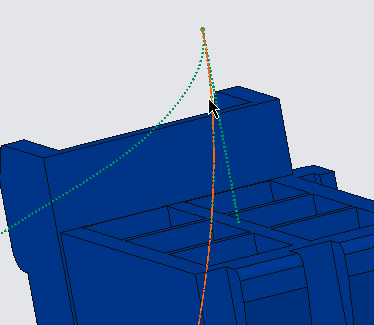
3. If there are multiple branches at the selected location, select the reference network segment about which you want to define the tangency.
4. Click the arrow next to  Flip Direction and click Display Tangency to view the tangency arrow.
Flip Direction and click Display Tangency to view the tangency arrow.To Flip the Direction of the Network Branch
1. Click Fix Tangency to flip the direction of the network branch at the selected location.
Fix Tangency to flip the direction of the network branch at the selected location.2. When prompted, select a location.
3. If there are multiple branches at the selected location, you are prompted to select a segment to flip.
4. When prompted select the reference branch segment about which you want to flip the segment chosen in step 3.
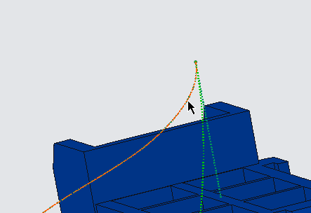
The selected segment is flipped with respect to the reference segment.
5. Click the arrow next to Fix Tangency and click Display Tangency to view the tangency arrow.
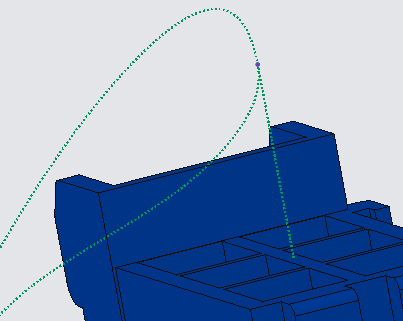
Fix Tangency and click Display Tangency to view the tangency arrow.To Remove the Tangency of the Network Branch
1. Click the arrow next to Fix Tangency and click Clear Tangency to remove tangency of a network branch at the selected location.
Fix Tangency and click Clear Tangency to remove tangency of a network branch at the selected location.2. Select the network location.
Click the arrow next to Fix Tangency and click Clear Tangency to remove tangency of all branch locations.
Fix Tangency and click Clear Tangency to remove tangency of all branch locations.